CableMod is widely known for its cables and adapters, and put me in a challenge. To push to the limit its cables. A challenge that brings music to my ears because it combines heat and power, lots of it.
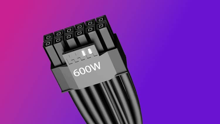
CableMod sent me some cables they wanted tested to the max, and I was more than happy to accept the challenge. The cables belong to their 12VHPWR 90 Degree line, which, by the way, can confuse users because there is absolutely NO difference between the cables that the ATX v3.0 and ATX v3.1 PSUs use, and the same goes for PCIe CEM 5.0 and 5.1 GPUs. The cable IS the same. The only difference is on the PCB header used on either the PSU’s modular board, which is not required to be 12+4 pin type. The ATX spec states that 2x 8-pin sockets can also be used. In any case, the GPU’s PCB header has to have 12+4 pins.
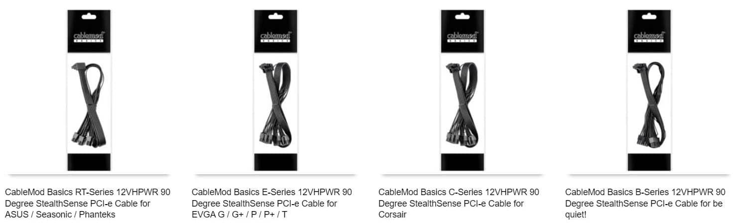
Although the cables have the term “12VHPWR” on their line description, they can be used by compatible ATX v3.1 PSUs. Depending on your PSU model, you must select the corresponding cable. All share the same price of 30 euros.
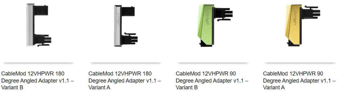
Besides cables, CableMod also sent me angled adapters for users who want to use the stock cables. Although the term “12VHPWR” is also present, these adapters feature a 12V-2×6 header on the end side. I asked CableMod about that, and they mentioned that they would fix the naming scheme to avoid confusion.
Test Methodology
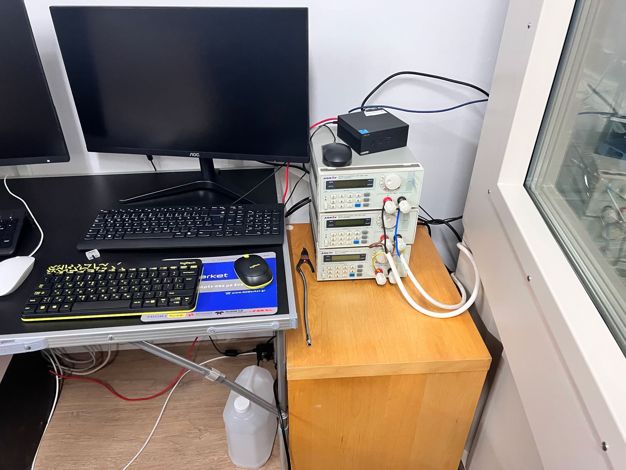
After introducing the cables and the adapters, I will reveal how I will approach this evaluation. Initially, I thought to remove my RTX 4090 from the box and connect it to my GPU test station, which has a Powenetics V2 system installed, and throw the entire set-up in the climate chamber, where I would dial 50°C and leave it running for an hour or so. I soon realized this was not enough, so I found a PCB and started building a test fixture, which I would use to connect three electronic loads and a Seasonic Vertex GX-1200 PSU, with a CableMod cable in between.
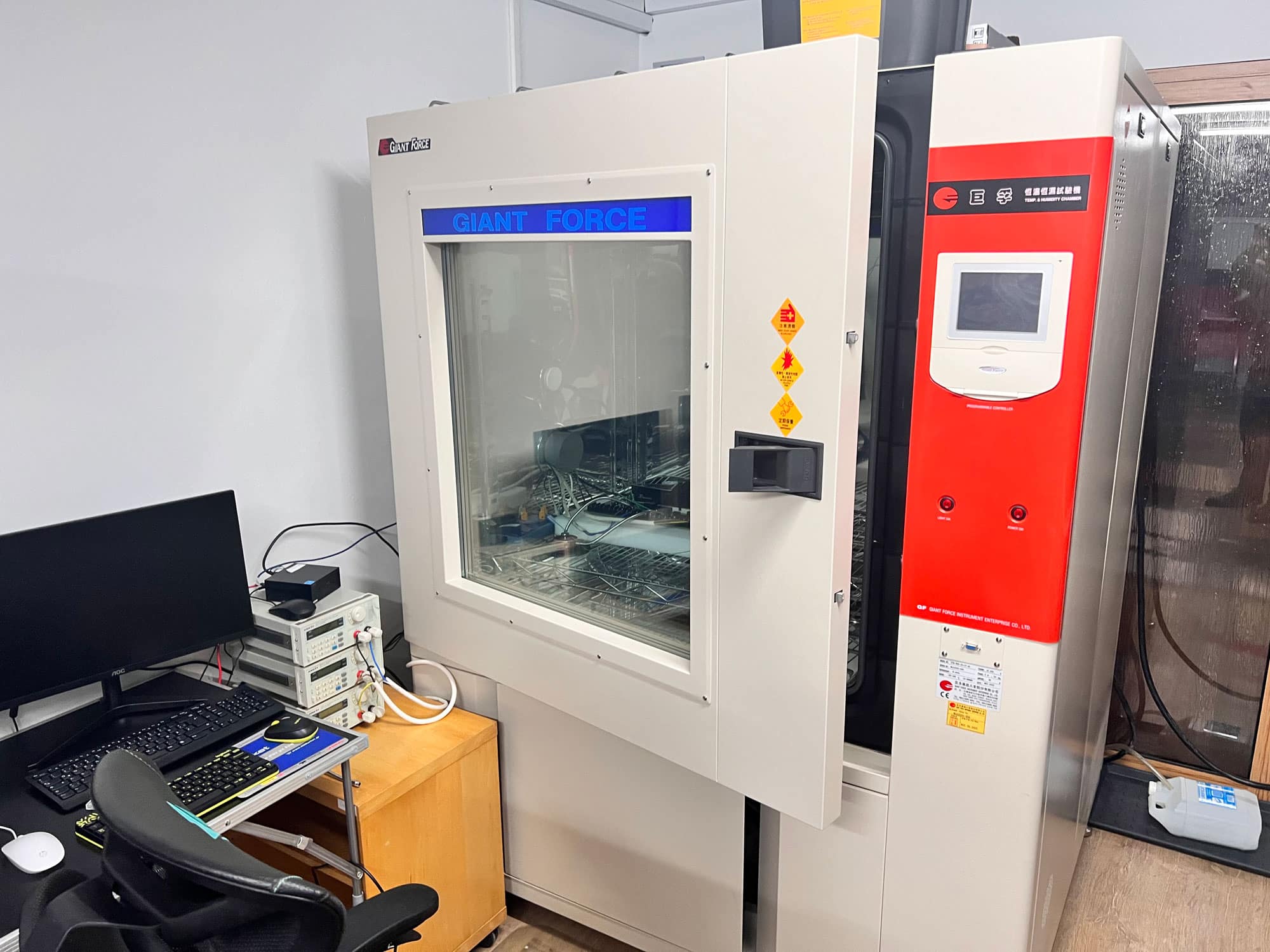
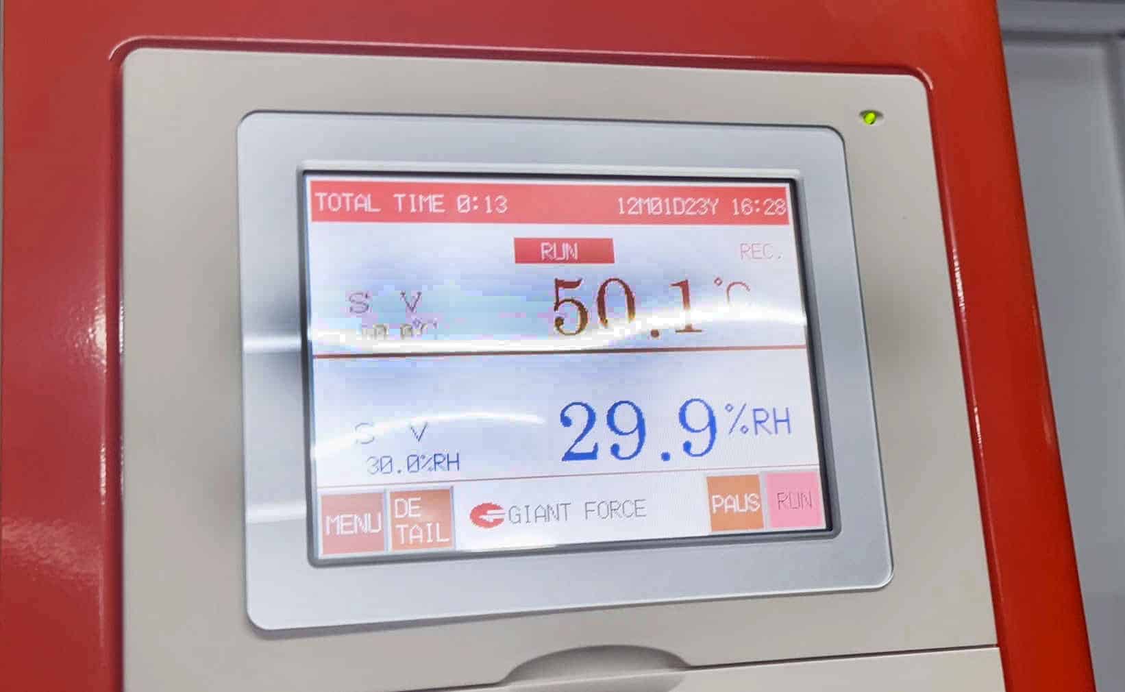
The climate chamber will be set at 50 degrees Celsius and 30% humidity, and the electronic loads will allow me to apply an adjustable and steady load to the cable and the connectors.
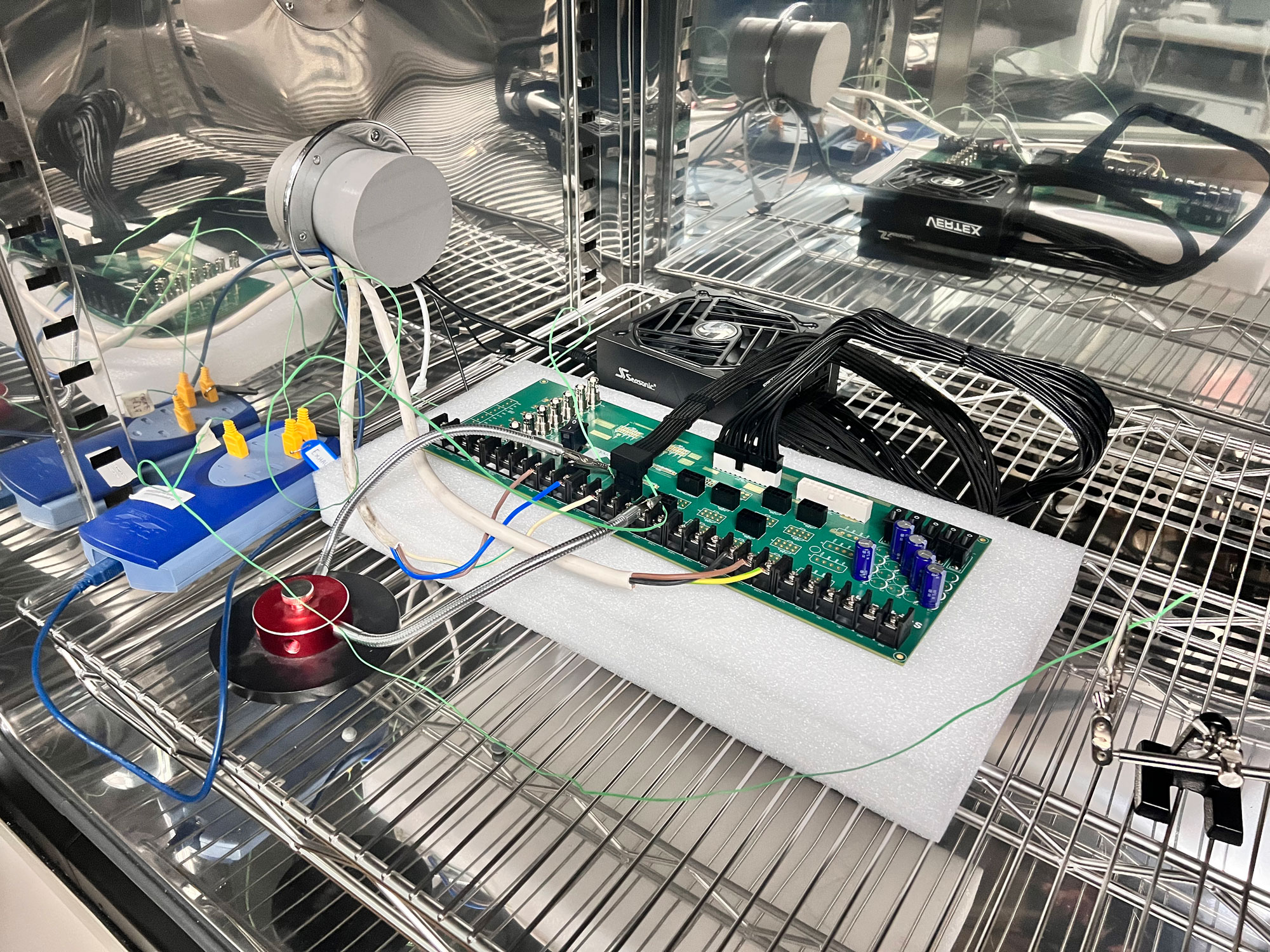
A Picoscope TC-08 will log the temperatures of the CableMod cable/connector through a pair of K-type thermocouples that come in contact with it. The thermocouples are not tightly secured on the connector, but they will still provide early information in case of a sudden temperature rise, which can lead to melting or even to a fire.
The test fixture in the photo above was a plain PCB 5-6 hours before that photo was taken. I soldered everything you see within for this evaluation’s needs. Since these fixtures handle lots of power, you must be extra careful during soldering. But I guess I will use the same fixture and some of the upcoming tests, so all this trouble wasn’t for nothing (I hope so, at least!)
Testing Results
We shot a video showing everything more intuitively, which I will include in this article once it goes live. During the first 8-10 minutes, I had a steady load of 55A, which then increased to 60A, and during the last minutes of the test, after 65-68 minutes of loading time, I increased the load to 65A. Despite being 10A above the limit, temperatures remained steady.
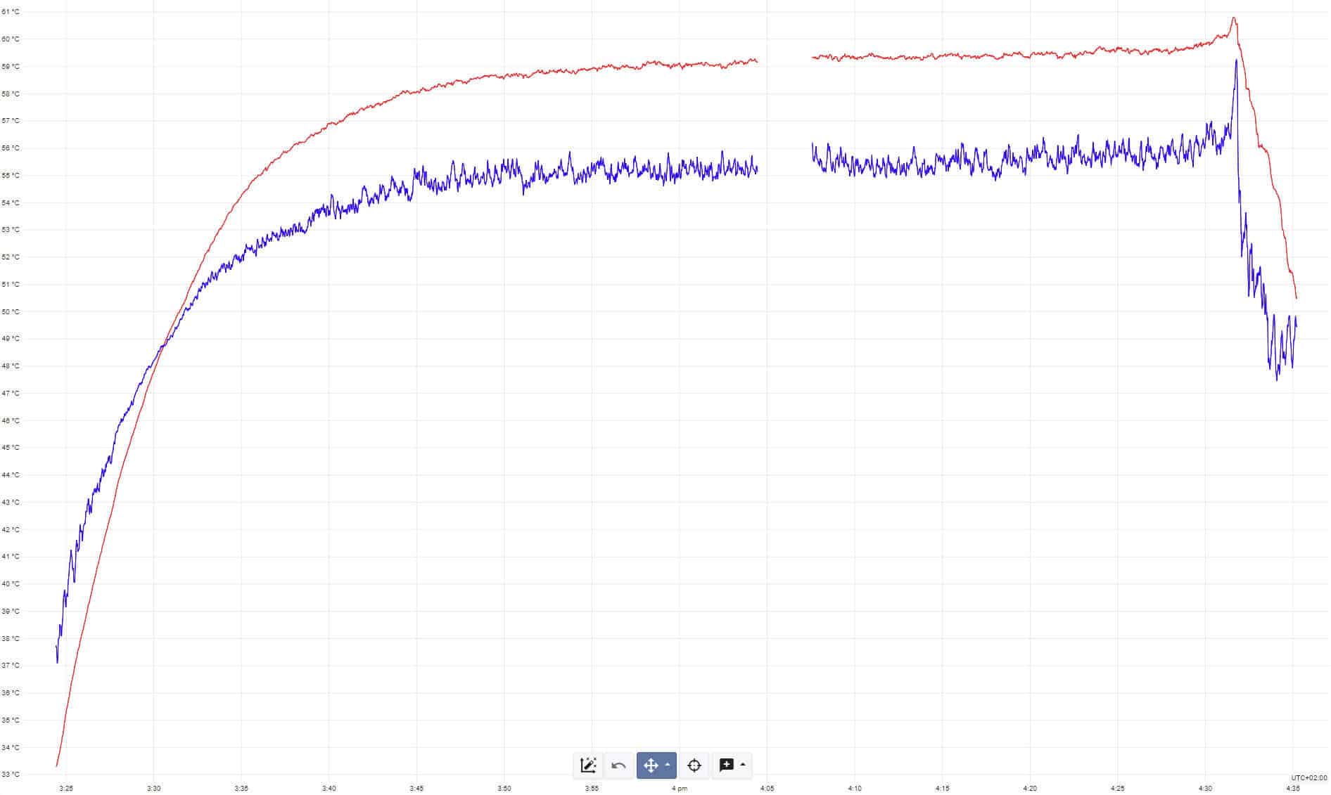
The measurement gap is because one of my engineers accidentally shut down the UPS, powering the PC that controls the temperature logger. Thankfully, I didn’t lose all the data. During the end of the test, the temperature inside the chamber increased once I opened it, reaching 55C ambient. I continued logging temps to see how fast the connector’s temperature would drop. In no case did I notice increased/alarming operating temperatures, a sign that the pins inside the connector are highly conductive and of good quality. If the pins have increased resistance or the connection to the PCB header is improper, lots of thermal power is lost under high amperage, leading to increased temperatures and melted connectors.
CableMod’s cable proved to be way more tolerant than the PCIe CEM 5.1 requires, and their angled connectors will be a lifesaver for many users. It seems strange that they decided to use three 8-pin connectors on the PSU’s end when even the ATX spec mentions that 2x 8-pin sockets are enough. They probably went overkill there just to be safe, and I cannot blame them, given what you can find on Reddit and forums.
I didn’t notice ANY problems during my extended testing, but a piece of advice. You have to ensure the connector is properly connected to the PCB header. As I stated in this article below:
Although the new 12V-2×6 PCB header provides enhanced protection compared to 12VHPWR, it is still highly advised to double-check that the connector is full of the PCB header. The quality of the cable you will use matters, of course, and let me repeat that the cable is the SAME whether you have an ATX v3.0 or, an ATX v3.1 PSU, or a PCIe CEM 5.0 or 5.1 GPU. The difference is only on the PCB header.
If you have any questions, leave a comment or, even better, join our discord server and post them there.
If you are searching for a future-proof PSU, check my Best ATX v3.0 PSUs article. You help me a lot by using my affiliate links, which don’t increase the product’s price. I get a commission from Amazon every time you do it, which can make a difference for me, especially now that I am on my own, working exclusively for my media and not for someone else.
I wish they would add newer FSP models to their configurator, especially the Hydro Ti PRO 1000W. I tried asking CableMod but they gave a pretty noncommittal answer. The pinout might be the same as the older models for all I know, but I don’t want to commit to a purchase without being certain.
I used cable mod when I oc’d my gpu and on 2×8 pin they only started to melt at 600 watts or so. Good result id say.