ATX v3.1 & PCIe CEM 5.1 are official! The ATX v3.0 spec was released in February 2022, and there was an update one year later. On 13 September 2023, its successor, the ATX v3.1 spec, came out. The major changes/additions in the new spec are the new 12V-2×6 connector, which replaces the 12VHPWR one, the shorter hold-up time, and the new settings on the sense pins of the 12+4 pin connector for 150W and 0w sustained power levels. There are some more changes, which we will analyze in this article.
The new ATX v3.1 is a thing, and in the following paragraphs, I will share with you all the changes.
The 12VHPWR connector’s PCB Header’s internal pin lengths have been modified. Therefore, the connector has been given a new name. The 12VHPWR connector name has been changed throughout the document to “12V-2×6”. The “Cable Plus” side of the connector has not changed and is compatible with the new PCB header connector definition.
This is a significant change. We have changes to the 12VHPWR connector, which led to 12V-2×6. I will analyze all the differences between these two connectors in the following paragraphs.
Reference documents to PCI-SIG document about PCIe CEM 5.0 changed to Rev 5.1. Previous ECNs have been removed as these changes have been included in Rev 4.1. Changed language in section 3.1 to list how PCIe CEM Rev 5.1 now incorporates all previous ECNs.
This is self-explanatory. Intel followed the PCIe CEM 5.1 guidelines in the ATX v3.1 spec, which introduces the 12V-2×6 connector.
Updated Table 3-1 with two new additional columns.
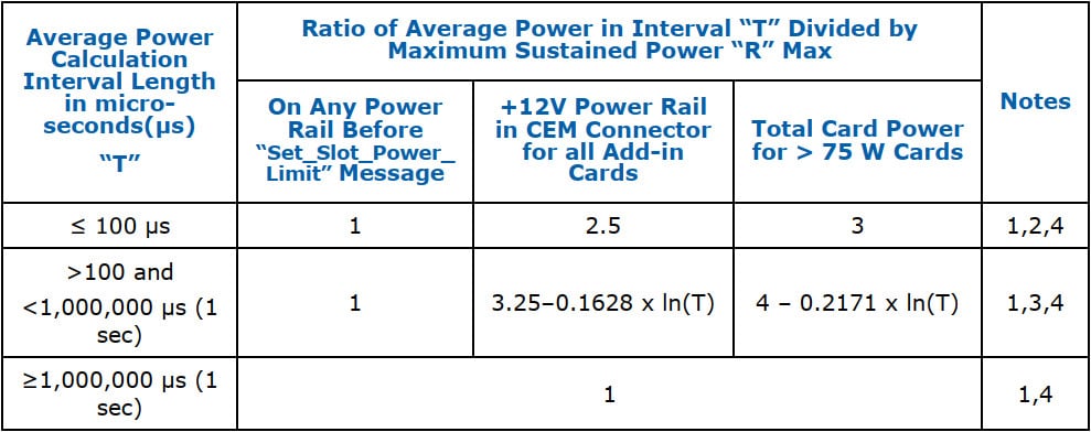
This table is of enormous interest! According to the new ATX v3.1 spec, power excursions are also permitted on the 12V rail drawn from the baseboard through the PCIe Add-in Card connector’s card edge, in other words, the mainboard’s PCIe slot! No excursions are permitted, though, on the 3.3V and 3.3Vaux signals. These two rails must continue to abide by the legacy Add-in Card power limits.
So far, the 12V rail was limited up to 5.5A on the PCIe slot, and according to the new ATX v3.1, it can have spikes up to 13.75A for 0.1ms or 165W (with a nominal voltage of 12V).
Updated Figure 3-1 to show two new Power Excursion limit lines. PCIe CEM Slot (Blue) and ‘Before Software Configuration” message (Green) lines are new.
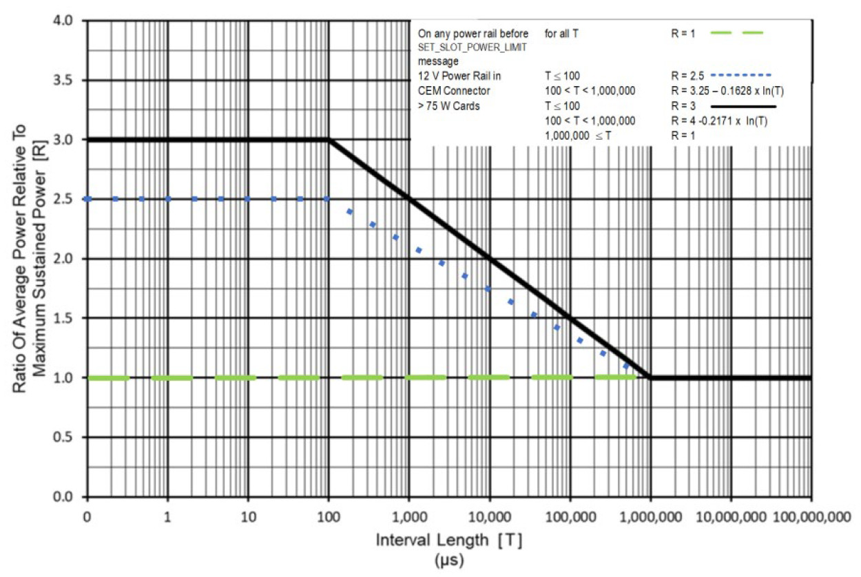
I want to see mainboard manufacturers and reviewers testing the mainboard’s slot and if it can handle power excursions at 12V and up to 13.75A. Powenetics to the rescue for this job!
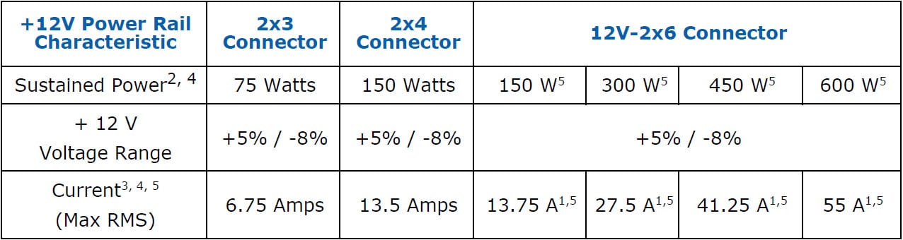
Updated Table 3-5 to show the different current values for the different power values that can be used with the 12V-2×6 connector.
Updated Table 3-6 with new sense line definition for 150-watt and 0 0-watt sustained power levels.
| SENSE0 | SENSE1 | Initial Permitted Power at System Power Up | Maximum Sustained Power After Software Configuration |
|---|---|---|---|
| Ground | Ground | 375W | 600W |
| Open | Ground | 225W | 450W |
| Ground | Open | 150W | 300W |
| Short | 100W | 150W | |
| Open | Open | 0W | 0W |
In the 12VHPWR connector, there were no oW settings, and for 100W and 150W power at system power up and max sustained, the setting was open-open instead of short.
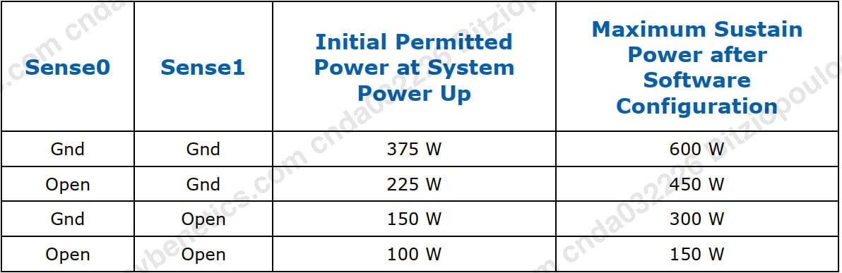
The SENSE0/1 setting of the 12VHPWR connector. NVIDIA has to change the graphics cards with the new 12V-2×6 connector to replace the open-open scenario with 0 Watt, and PSU manufacturers have to short the SENSE pins for 150W max output. So far, I haven’t seen a PSU with a 150W set 12VHPWR, so there won’t be any issues. This is why all brands used the GND-GND setting for the total 600W, I guess.
Updated Table 4-3. Note 6 has been added to show that Dynamic Load testing for the “-12V” rail has moved from Required to Recommended.
The -12V rail, which is optional from the previous specs, is not required to be tested with dynamic loads if it is present. I highly recommend that all PSU manufacturers remove this rail since it is no longer used so they can boost efficiency and decrease production costs.
Added Table 4-8 to show the new Voltage Hold Up time levels. Before, only a required level was 17ms @ 100% load. Now, there is both a Required level and a Recommended level.
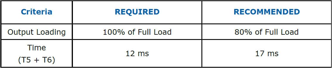
This is a big step backward if you ask me. I’m afraid I have to disagree with the change at 12ms @ full load from 17ms. This is wild because, in this section, ATX v3.0 PSUs are better than ATX v3.1 ones! Intel contacted UPS manufacturers to confirm that the switch to battery time is lower than 12ms. Still, in any case, hold-up caps age, losing capacity, and besides that, it is always better to have more reserve power. On the other hand, I know that the bulk caps are expensive, which will help manufacturers lower the production cost. Moreover, the new spec is a blessing in SFX units with little space for high-capacity bulk caps since they will finally get a Cybenetics ATX v3.1 “Pass” badge!
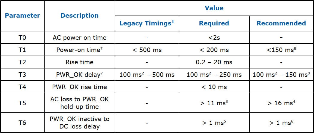
Updated Table 4-10 with the T5 value has both Required and Recommended level that corresponds to changes in Table 4-8.
| ATX v3.1 | ATX v3.0 |
 |
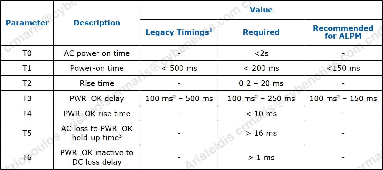 |
In ATX v3.1, T5 has a recommended value of >16ms hold-up time but with 80% load and not a full load. The same applies to T6.
Additions to Section 5.2.2.4.3 for new 12V-2×6 connector drawings. Figures 5.4 to Figure 5-9 are all updated or new.
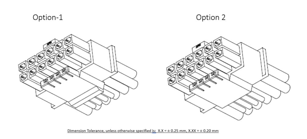
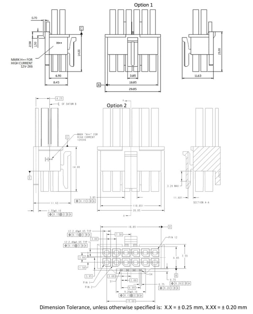
Some drawings of the 12V-2×6 connector.
Updated to Section 5.2.2.4.3 – Cable Plug Connection Recommendation has been replaced with technical details to look at for internal connections.
Like 12VHPWR, the 12V-2×6 power connector has been designed to deliver up to 600W of 12V power to the PCIe Add-in card. This connector has twelve power pins with 3.0mm spacing and four smaller contact pins carrying the sideband signals.
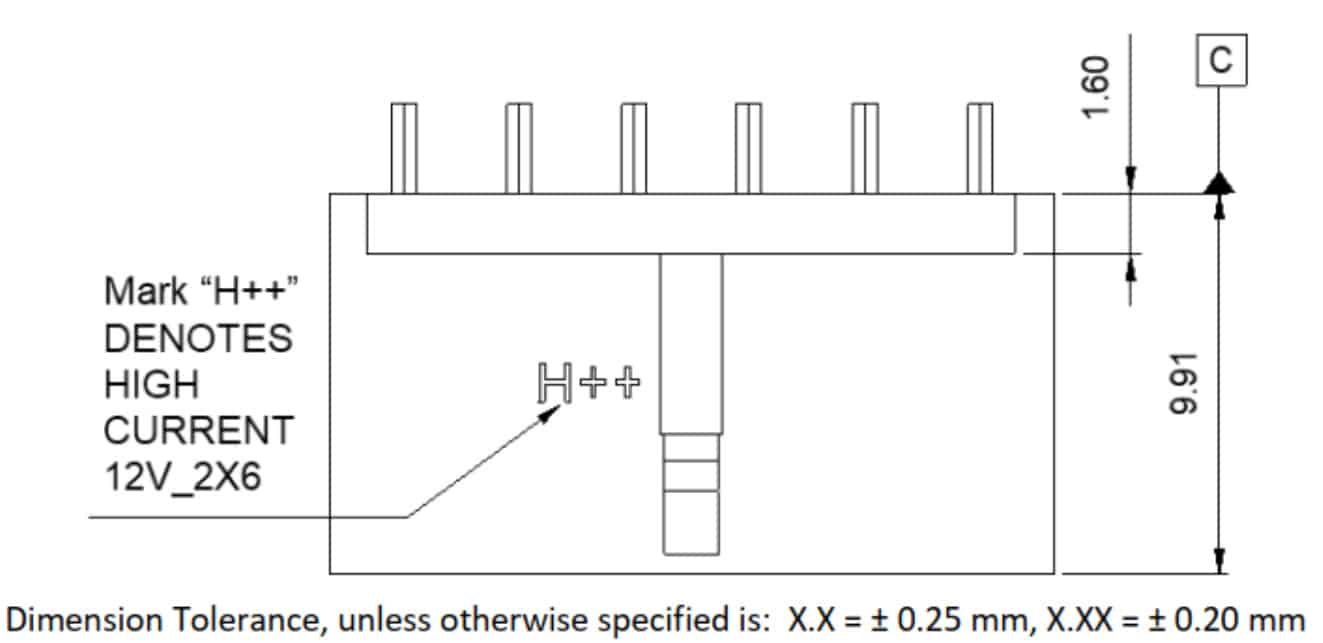
The twelve power pins have a 9.2A per pin/position current rating at 30C T-rise above ambient temperature conditions at 12V, energizing all twelve contacts. This means that the pins should be able to deliver up to 1324.8W! The connector’s body must have a label or embossed “H++” characters to indicate the support of 9.2A per pin or higher. The pin contact material has to be Copper Alloy. The wire thickness is 16 AWG, while the wire size is 28 AWG for the sideband signal pins.
The significant improvements introduced with the 12V-2×6 connector are the following:
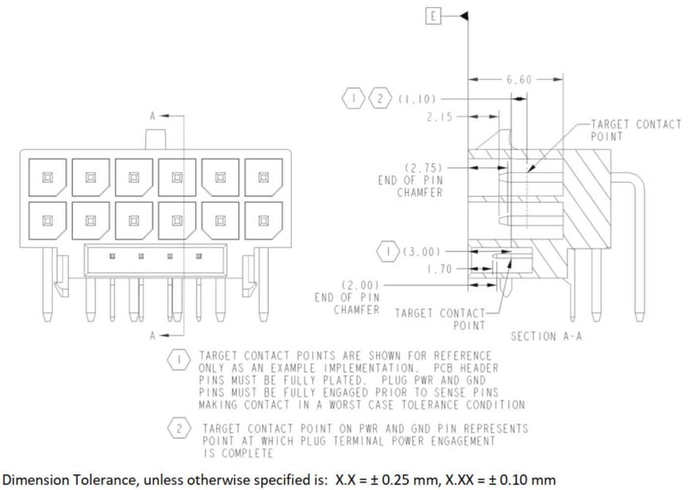
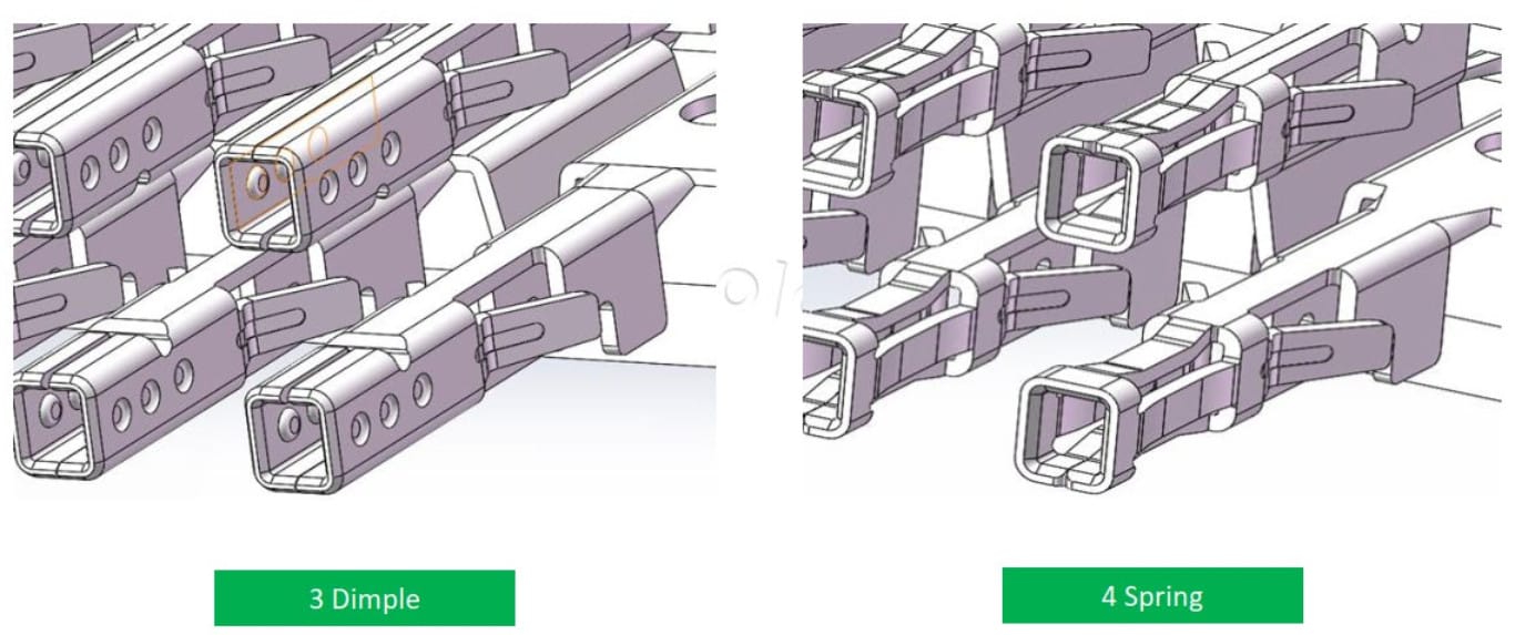
The power pins have been lengthened, and the sideband pins have been shortened in the PCB header to ensure the power pins’ fist-mate/last brake engagement. In other words, the new design ensures that the sideband pins engage only after the power pins are sufficiently mated. So when the graphics card “sees” both SENSE pins are open, its power state is zero, and it cannot draw any power to avoid any connector “melting” issues. This zero-watt state wasn’t present in 12VHPWR, and it is a clever way to avoid problems since an open-open condition means that the connector is not correctly connected or just absent.
The power supply must be able to provide these updated SENSE0/SENSE1 encodings to the cable to ensure compatibility with PCIe CEM 5.1.
Conclusion
The new 12V-6×2 connector is much safer than the previous one. On top of that, according to my sources, new pins are used, ensuring minimizing resistance thanks to the new SENSE0/1 states and the shorter corresponding pins; even if you don’t fully connect the 12V-6×2, you won’t face any issues. Actually, I already tested that during a visit to LINEWELL (wait for the video!), a cable manufacturer cooperating with Asus, Corsair, Seasonic, Great Wall, and other brands and OEMs, and I can say that I was impressed.

I am currently on a business trip to China, but I devoted several hours to offer you this article. My best to the people at LINEWELL for their fantastic hospitality. Although I am thousands of miles away from my home, I felt like I was at my home base. Many thanks also to Daltrey, Amy, Chris and Tim!

I also had the chance to meet with Jon (Gerrow) again, aka Jonnyguru, after several years. It is always nice to meet with good friends! Jon, I hope you don’t mind that I shared this lovely photo of you with our readers. But they deserve to know the Jonnyguru who inspired me to start PSU reviews 14 years ago!
Hey Aris I found and bought a closed box and official seller hx1500i 2022 for 220 dollars. Will it be good with 4070 ti super? I know it is unnecessarily powerful but The $220 price was enough for me to buy it.
it will be fine.
Hi Aris,
Thank you for your amazing work and coverage during this ****show that Nvidia created. Would it be better to use something like Thermal Grizzly’s wire view with 3 PCIE connector on an 3.0 PSU that isn’t 3.1? Or would going with Corsair or Super Flower’s native cable enough? Can we use both the Corsair cable along side the Wireview adapter (16 pins to 16 pins)?
To be frank, I haven’t checked Thermal Grizzly’s wireview adapter, so I don’t know how it works. In general I strongly advice to avoid ANY kind of adapters, after Cablemod’s problems. Just go with a native cable, way safer and better.
Just a note about the following: ‘The twelve power pins have a 9.2A per pin/position current rating at 30C T-rise above ambient temperature conditions at 12V, energizing all twelve contacts. This means that the pins should be able to deliver up to 1324.8W!’
In a 12pin power connector, 6 pins are for power and 6 are for ground/return path. So the power that can be delivered is actually 6*12*9.2A = 662.4W. All pins are still energized at 9.2A.
I was about to comment the same. Half of them are ground pins!
The video at the Linewell lab appears to show an unannounced and potentially ATX v3.1 Asus ROG power supply. It must be a replacement for the Thor Platinum II adding 12V2x6. Hopefully still a modified Seasonic.
On closer inspection its an ROG Loki. It would be interesting to know if the PSU end of the cable is connected to a 12VHPWR or revised 12V-2×6 connector.
Please let us know when the new atx 3.1 psu’s become available. Will some just use an updated connector during production like nvidia has done? Thanks
Do you have any information on the release date for the new FSP PSUs line-up? Example below:
Hydro G PRO ATX3.0(12V-2×6) 1000W Model: HG2-1000
https://www.fsplifestyle.com/en/product/HYDROGPRO1000W_12V2X6.html
Or would it be better to wait for the ATX v3.1 & PCIe CEM 5.1 PSUs to come to hit the market? Thanks!
As a user’s main concern, another point is how compatible the ATX3.1 cables are with 3.0.
For example, as mentioned by several previous commenters. Will a PSU with old 12+4 pin socket supply work with the new 12+4 pin to 12V2x6 cables?
Looking forward to your response~
yes.
Thanks for the reply. I almost got it.
That is say. Although the “power side connector” of the PSU cable remains unchanged,older ATX3.0 PSUs still do not have access to the protection features of the new ATX 3.1 standard via the “12V-2×6 cable” that comes out of the “old 12+4pin connector” (if provided by the manufacturer).
In the last photo, Johnny is conducting the most important part of testing the new ATX standard! 🙂
Hi Aris,
What will be the compatibility with pcie 3.0 and 12hvpwr (specially psus with 12hvpwr on the psu side like be quiet)? Will I need a new cable? Or could I connect a 12hvpwr cable to a future gpu with the new 12v2x6?
Corsair answered this question
“So what does this mean if you’ve already got hardware for 12VHPWR? Fortunately, existing 12VHPWR cables and adapters will work with the new 12V-2×6 connector as the specification is backwards-compatible. You’ll begin seeing new hardware, such as graphics cards, come out with the 12V-2×6 connector onboard and your current cables will work assuming you’ve installed everything correctly.”
crmaris wrote:
“I want to see mainboard manufacturers and reviewers testing the mainboard’s slot and if it can handle power excursions at 12V and up to 13.75A.”
Are you saying that @crmaris is wrong and that all mainboards with a PCIe slot can handle those power excursions by default, was this some kind of joke that I didn’t get or am I missing something?
So as someone with an ATX 3.0 PSU and a RTX4090. What should I do to ensure maximum safety? Contact my PSU manufacture and acquire a 12VHPWR to 12V-6×2 cable? Or is it safer with a 3×8 pin to 12V-6×2 cable? Or maybe it doesn’t matter since the my psu and 4090 still use the 12VHPWR connector?
From what I have looked up about this topic the cable is half the battle. So if you have the 12v 2×6 cable nothing changes if you are still using an ATX 3.0 PSU and a graphic card that uses the 12vhpwr standard. First you would need a PSU and a GPU that uses the ATX 3.1 standard to make use of the new safety features. And as far as the old cable it doesn’t matter if you have a 100x 8pin to 12vhpwr cable because the connector is where the problem is. Just be sure your cable is fully inserted. If you make any bends near the connector it won’t cause a problem if you double check it is fully inserted after the cable is bent. And be sure there is no stress on the connector from the bend for it to be able to loosen up over time as it heats and cools. It’s been a problem for a lot of people but not for everyone so you should be fine since you will be taking extra precautions.
Does PCIe CEM 5.1 specify anything that allows the add-in card to figure out whether it’s in a slot that supports the new power excursion limit?
The slot doesn’t need to support the power excursion. The PSU does.
lol
crmaris wrote:
“I want to see mainboard manufacturers and reviewers testing the mainboard’s slot and if it can handle power excursions at 12V and up to 13.75A.”
Are you saying that @crmaris is wrong and that all mainboards with a PCIe slot can handle those power excursions by default, was this some kind of joke that I didn’t get or am I missing something?