
We started having nightmares again with the 12V-2×6 cables and connectors, and we need to find a solution to put an end to this issue once and for all!
Many thanks to our mega sponsor, Montech, and our two additional sponsors, FSP and Super Flower, for helping with our trip to the US to investigate the RTX 50 meltdown further!
It seems that NVIDIA doesn’t plan on doing anything about that short-term and doesn’t want to pressure the board partners to find a standard solution to this pressing matter. Only Asus, to the best of my knowledge, since I don’t have any access to most RTX 50 models, in its super-expensive RTX 50 Astral models, has included current monitoring per pin on the 12V-2×6 connector. Still, I cannot comment much on this since I haven’t tested any of these models yet.
According to the data that I got from the Asus GPU team, it is only a monitoring solution. It cannot work for load balancing the GPU, which is not as easy as it sounds since if/when the PWM controller senses that some of the 12V-2×6 pins underperform and some deliver way higher current, it isn’t easy to equate the path resistance on each one at the fast rate required by the dynamic loads, to make current flow equally! At the same time, the GPU needs a specific amount of power to be delivered to continue its current operation. Instead of load balancing, the PWM controller could just “cut” power to the GPU to ensure that no power input points are way above a safe limit. As you can see, this can be a long and complex discussion!
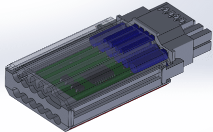
We are working on a prototype. We won’t use this exact design, most likely because I don’t want the connector that long. I want a more elegant solution. I’m waiting for your thoughts, though!
Whatever the case, and given that NV doesn’t care, I am trying to find a solution that will help all users be and feel safe since I get so many emails from worried users every day asking whether they will face issues with some specific hardware configurations.
I have already checked ASRock’s approach with the thermistor in the middle of the 12V-2×6 connector on the GPU side, and it works. However, I am afraid it won’t be enough for some cases where the pins will start to get hot on the sides of the connector, and the centered thermistor will get the relevant data rather late.
This is why we are working on two different approaches so far on a cable with an embedded circuit taking power from the 12V rail:
- With thermistors attached as close as possible to all six 12V gauges on the GPU side.
- With six current shunts to monitor current on each of the power transmission lines of the cable.
Over Temperature Protection (OTP) approach. The 12V-2×6 connectors Sense 0/1 pins are set to open by the circuit mentioned above, so the GPU’s power circuit is set to a kind of “safe” mode where it is not permitted to draw any power.
Over Current Protection (OCP) approach. Sense 0/1 are set to open when a current higher than 10-12A is sensed for a period exceeding 2-3 seconds (we will fine-tune OCP’s settings through real testing). We have to set OCP’s reaction to slow so as not to have shutdowns under transient loads, which are typically much shorter (in time period) and don’t directly affect the cables’ or the connectors’ condition. Only sustained high currents matter here, and these are the ones we will deal with.
Of course, the perfect solution is to have both OTP and OCP on the cable, but this would affect the production cost. On high-end expensive PSUs, adding a few dollars more for the ultimate protection won’t be a real issue, but we also have to think about badge-oriented users. If you ask me, there is no price for protection features.


Sounds great. Good to see you guys putting effort in a working solution! Thank you so much!
Hope you make a 90 degree option too.
Till then I am using the Asrock Psu + wireview pro and going for a Astral.I guess this should be ok enough till then not sure how much more I can do myself
Is there any news regarding this solution?
I would definitely be interested in a product like this! Any updates on availability?
Can I sign up somewhere to be notified when this is available for purchase?
I am waiting for the prototype samples for evaluation. Need to be 100% sure that the final product will be safe.
We will make a video and article here once we have something ready.
Regard Magister Akuntansi
How does CPU clock speed (GHz) affect computer performance?
So the problem is no longer the connector, since a 12V 2×6 is being used, but rather the power delivery, which causes overheating and thus the melting of cables? If NVIDIA doesn’t find a solution… currently, would the only option be to create an adapter, still with a 12V 2×6 connector, equipped with an internal chip capable of properly managing the power distribution to the GPU?
would the sense pins actually make the Device respond after initialization? i’m not sure that the Device (GPU) checks those signals after it finishes initializing.
NVIDIA is to blame. let NVIDIA make its boards like they did in 3000 series cards. if not mistaken the 3000 series cards had balancing Amperage checking to their boards.
Use a voltage sensor at the GPU end of the cable and if the voltage along the cable drops more than 0.2v between the PSU and GPU then have the power supply shutdown with an error code indicated by a flashing led on the power supply. This would mean that the cable would have to be of a satisfactory quality and that the connecters be properly seated to prevent an immediate PSU shutdown when the graphics card is being worked hard and drawing lots of power
The problem’s on the board side though, can’t measure that from the cable, although you can get it via the GPU in software via the current shunt. There are some ways to monitor this in software already, maybe HWiNFO can add a virtual sensor for the Vdroop between card edge (PCIe +12V Input) and aux power (16-pin HVPWR). I’m actually seeing better voltage on my 2×6 than the card edge.
This is a stupid and necessary bandaid. The connector is underspecced for the job of high power delivery. There are already connectors that can do the job better without melting. Anyone still banging on about user error is just wrong, it is defective and needs to be scrapped and the GPUs recalled.
> Anyone still banging on about user error is just wrong, it is defective and needs to be scrapped and the GPUs recalled.
Can you provide the math for how a cable, which contains terminals comply to the PCIe 5.1 CEM specification, can result in a thermal failure?
The connector is fine for high power delivery, part of the issue is user education about how durable these connectors are. Most connectors inside your computer are only rated for 25 mating cycles, they’re semi-permanent and should be treated as such.
Very interesting, I wonder what cables NV used when they were testing the cards while in development. I am hearing that even the 5080 is burning out which is really bad. Good luck Aris.
Very interesting! Maybe I’m being naive, but even if the power draw of the GPU is very dynamic, aren’t the resistance ratios of the individual connections pretty much static? Or do the ratios fluctuate wildly along with the power draw?
There are various hypotheses floating around, one of them is that the connector is subject to thermal cycling stresses in the field which the lab testing does not reveal, and that these stresses may result in degradation of the connector assembly.
Just change the voltage…
Or use thicker wires/connectors…
Either way…
I’m not sure you can rely on cutting sense 0/1 while the card is in operation, per the spec (at least what we can see in what Intel incorporated in ATX 3/2.1a) these pins should not transition while the card has power at the +3.3V at the card edge.
> These SENSE signals must not change state while PCI Express CEM Add-in Card edge has the main +3.3V applied. Support for the SENSE0/SENSE1 sideband signals is independent of the two optional sideband signals defined for the 12V-2×6 connector (CARD_PWR_STABLE & CARD_CBL_PRES#).
https://edc.intel.com/content/www/us/en/design/ipla/software-development-platforms/client/platforms/alder-lake-desktop/atx-version-3-0-multi-rail-desktop-platform-power-supply-design-guide/2.1a/sense0-amp-sense1-required/
That is a great comment you left there! Thanks!
When I was playing around with this idea, I was leaning toward doing a mobo power switch intercept (like watercool do), pull it down input power drops, then have a small supercap to keep a fail LED/buzzer active via a latch. Hope this works out, anything which gives people some peace of mind and gets them to stop playing with semi-permanent connectors is a good thing.
The design is obviously underrated for normal current levels. Monitoring current is like fitting a smoke alarm when you really need to stop the building catching fire.
I’d solder better connectors (higher rated, gold plated, use more pins) and connect direct to the PSU with heavy gauge wires. It would likely invalidate the warranty but better that than having the connectors melt.
How do these boards comply with UL and/or CE standards? Connectors and cables that overheat and melt are a hard fail.
It’s fine at normal current levels if you have a connector that’s within spec, the spec being difficult to observe is what a product like this would be pretty good at fixing. Or better user education on how cable terminal wear affects performance of the system.
What about just using one thick cable?
You want to land #6 with a lug on your card? They can ship the cards with little torque wrenches so people can appropriately torque their connector for proper resistance at the mating interface. And maybe then Lian-Li can sell you a gold-plated lug which will corrode the nickel or tin plated mating surface on your PCB, like they do 12v-2×6 cables.
https://blog.samtec.com/post/dissimilar-metals-in-mating-connectors/
https://www.molex.com/en-us/blog/gold-or-tin-vs-gold-and-tin
Hey,
Great Idea with the cable and please take into that many won’t have a lot space between the sidepanel and the GPU to fit a long solution that sticks out of the GPU.
If it’s possible make it a cable with a 90° angled connector.
We will put this board on the cable and yes we are also working on an angled connector.
I thought you would come up with something like this – good idea. I guess price doesn’t matter that much for 5090 customers, so as others said, you might want to consider both solutions for the product.
However, if it is directly incorporated into the plug, I worry it will be difficult to use in small form factor cases with limited space on the side. 😞 but maybe you’ll come up with a clever solution when thinking about it.
Wish you success with this idea!
RTX 5090 and budget buyer? Cmom lol
Please make more expensive but with best protection
I would honestly work together with Der8auer and make a new WireView that has this built in. If not, I hope there will be a Corsair Type4 and Type5 2x8pin to 12v-2×6 cable with this stuff, so I don’t need to throw my 400$ ATX 3.1 & PCIe 5.1 certified, 50-series ready HX1500i in the trash
Hello!
Please keep in mind that a cable solution needs to come in different lengths!!! I would be first in line to buy one, but I need at least 850mm long cable to avoid any extentions or adapters as I use a fractal torrent compact case and the run from the PSU at the top of the case to the GPU at the bottom is a long one.
Also, make it with 4×8 pin termination options on the PSU side so that people without ATX 3 PSU can get it too
Given that the problem is happening on high-end GPUs only, I don’t think we need worry about budget buyers for the PSU fix. If you can afford a $2000-$3000 USD GPU, then you should be able to afford a few more dollars for PSU features that protect your purchase.
As such, I’d say incorporate both types of protection.
I believe that it would be best to release several versions of the cable, as to cater towards every kind of user, budget oriented or not. However, the main GPU’s having this problem are the high tier ones (mostly 5090s and 4090s), which don’t appeal to budget users. Personally, wanting to buy a 5090 myself in the near future, I would much rather pay a bit extra to have a cable with both OCP and OTP and know that my gpu has the highest protection, rather than one of the two approaches, even if the difference in protection is minimal. Hope you can get one into the market soon! And I think you could also implement pre-orders, to fund part of the cost. I’d be more than glad to support such an effort, since from what I can see, Nvidia will do nothing to mitigate this issue. Thank you for all you do
It’s User Error Period. If The USER gives money/buys a product with a know poor design that leads to said product being damaged in normal/stated usage parameters then Only the User is to blame,point i am trying to make is…stop buying shitty products,nvidia a multi billion dollar company cannot be bothered to design a safe working plug and play product what a gpu in my opinion is,they know there is a problem and they wont fix it…why? They don’t care for us the ordinary customer,it’s very hard for me to believe that nvidia a mega corporation made such a poor design by mistake or by forgetting a “thing”,they want to innovate but at the customers expense…so no thx,lets see what they do with 6xxx series,i highly doubt they will do anything positive. 5xxx series even bigger disaster than 4xxxx in my opinion.
PS. thx to HWBusters for doing these investigations,your time is appreciated.
For how big some of the third party RTX 4000 / 5000 are, I wouldn’t mind if this custom cable could be designed in 90 degree variants as well! The current 3D model of the prototype will probably not fit in most mid-tower cases. Outside of that, I would probably test the cable to check if all PSUs could actually support the cable. You already mentioned that the pinout for the PCIE 5.0 connector it’s the same for all PSUs so it shouldn’t be a problem, but it would give some peace of mind if this could also be tested.
Also, in case an OTP solution is used, wouldn’t it be a good idea to also implement the thermistors on the PSU side as well? I remember a recent case where the PSU connector melted but not the one on the RTX 5090 FE. A summary of the case it’s mentioned at the bottom of this article (there’s also a video but it’s only in Spanish): https://videocardz.com/newz/geforce-rtx-5090-founders-edition-card-suffers-melted-connector-after-user-uses-third-party-cable
Bring back the multi-rail psus.😃
All of this drama would have been avoided if Nvidia kept 3090ti’s power delivery system.
It’s hilarious they implemented first and only on that card to “beta” test it, then decided to throw a working design out the window lmao.
Innovation at customers expense…get used to it
The 3090ti was only 450W, and octal current shunt monitors were not available until just recently. For thermal overcurrent protection, a single current monitor IC which can monitor all input circuits in a group is required, or you can’t respond to overcurrent conditions quickly enough (you’d have to depend on a microcontroller monitoring multiple current shunt ICs, which would be questionable from an engineering perspective).