Will my ATX v3.0 PSU or my GPU be compatible with 12V-2×6? This is what troubles most users from the moment ATX v3.1 & PCIe CEM 5.1 are official and the new 12V-2×6 connector replaced the short-lived 12VHPWR. This makes the owners of ATX v3.0 PSUs and also the owners of graphics cards with the 12VHPWR PCB headers wonder if their parts are now obsolete. In this article, I will explain everything you need to know, in plain words.
I have already written an article about the changes that the ATX v3.1 spec brings. You can find it here. In today’s article, I will focus on the most crucial change for most users, which is the replacement of the 12VHPWR connector with a new one called 12V-2×6.
In plain words, the following took place:
The 12VHPWR connector’s PCB Header’s internal pin lengths have been modified. Therefore, the connector has been given a new name. The 12VHPWR connector name has been changed to “12V-2×6”. The “Cable Plug” side of the connector has not changed and is compatible with the new PCB header connector definition.
In short, the 12+4 pin PCB header changes are these: the power pins have been lengthened, and the sideband pins have been shortened to ensure the power pins’ fist-mate/last brake engagement. In other words, the new design ensures that the sideband pins engage only after the power pins are sufficiently mated. So, while the graphics card “sees” both SENSE pins are open, its power state is zero, and it cannot draw any power to avoid any connector “melting” issues. This zero-watt state wasn’t present in 12VHPWR, and it is a clever way to avoid problems since an open-open condition means that the connector is not correctly connected or just absent.
To clarify, the cable connecting the PSU’s high power socket(s), either 12+4 pin or 2x 8-pins, to the graphics card corresponding socket remains the same. Only the 12+4 pin sockets (PCB headers) have the changes mentioned in the paragraph above. So, if you have a PSU with a native 12VHPWR PCB header on its modular board, you don’t get the benefits of the new connector. The same goes for your graphics card, of course. In other words, you can do nothing about it if your hardware uses 12VHPWR PCB headers unless you have good soldering skills. You must find and replace the new connectors on your PSU and graphics card! You should also flash a BIOS to your graphics card to interpret correctly the open-open sense scenario for 0 W, and your PSU should also be able to provide the new sense encodings to the card!
There aren’t many cases where the PSU’s connector had any problems, so if you have an ATX v3.0 PSU with a 12VHPWR PCB header, you will be fine. Buy a graphics card with a 12V-2×6 PCB header featuring the shorter sense pins and the longer power pins to be safe. There is only one catch: ATX v3.0 PSUs don’t send the open-open signal when nothing is connected to their high-power plugs.
| SENSE0 | SENSE1 | Initial Permitted Power at System Power Up | Maximum Sustained Power After Software Configuration |
|---|---|---|---|
| Ground | Ground | 375W | 600W |
| Open | Ground | 225W | 450W |
| Ground | Open | 150W | 300W |
| Short | 100W | 150W | |
| Open | Open | 0W | 0W |
In the 12VHPWR connector, there were no 0W settings, and for 100W and 150W power at system power up and max sustained, the setting was open-open instead of short. NVIDIA has to change the graphics cards with the new 12V-2×6 connector to replace the open-open scenario with 0 Watt, and PSU manufacturers have to short the SENSE pins for 150W max output. So far, I haven’t seen a PSU with a 150W set 12VHPWR, so there won’t be any issues. This is why all brands used the GND-GND setting for the total 600W, I guess. Still, the PSU should be able to provide the open-open scenario to the graphics card when the high-power connector is not connected to offer complete protection against power delivery issues.
12VHPWR vs. 12V-2×6 Cable Plug Connector
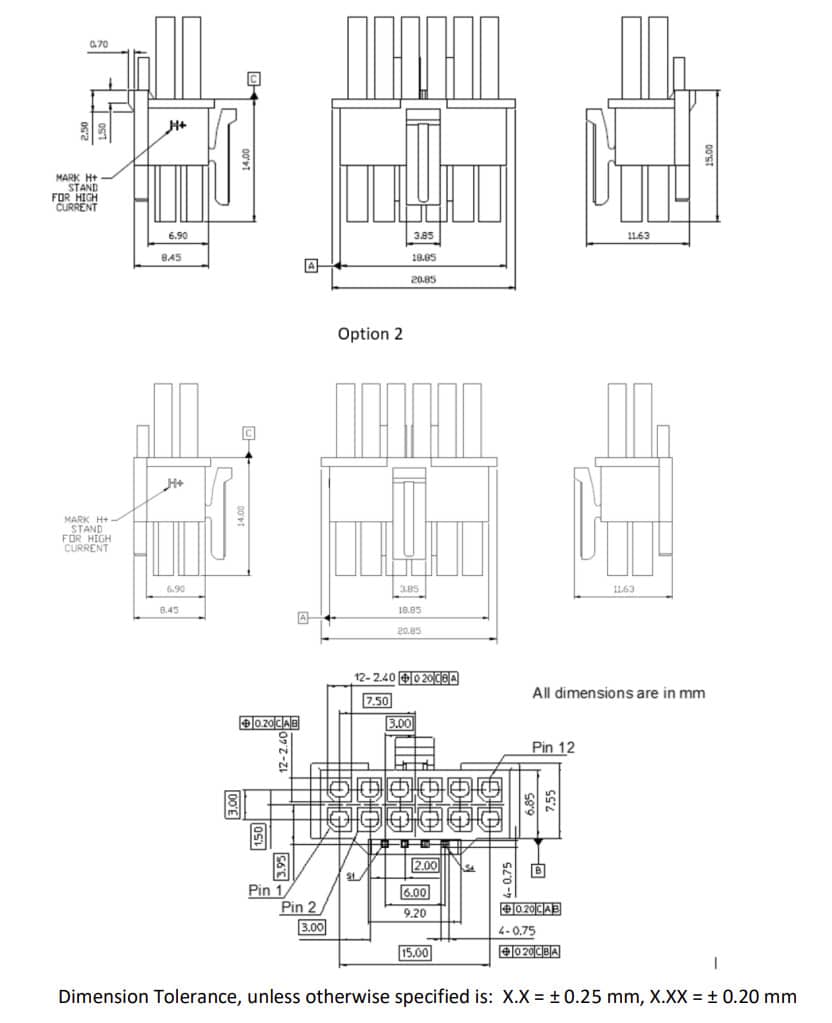
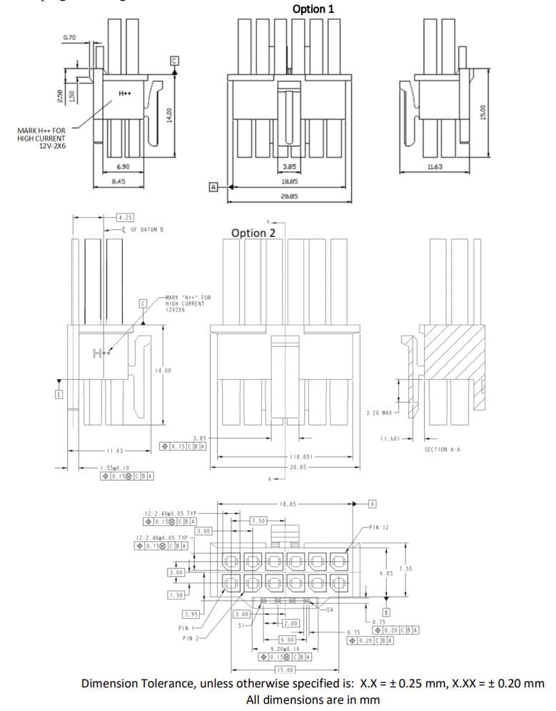
Since I want to show you some facts, you will find some drawings below comparing the 12VHPWR and 12V-2×6 cable plugs and PCB headers.
As mentioned in the ATX v3.1 spec, there are no physical differences in the 12+4 pin plug. The only visual difference is the “H+” mark on the 12VHPWR plug and the “H++” on the 12V-2×6 plug.
Again, there are no changes here on the plug.
12VHPWR vs 12V-2×6 PCB Header
Let’s move now to the PCB header, where all changes are.
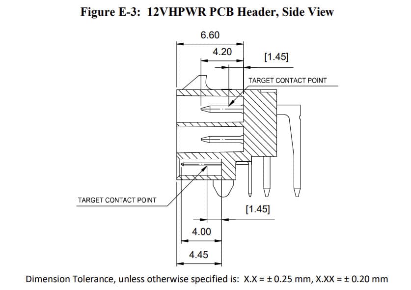
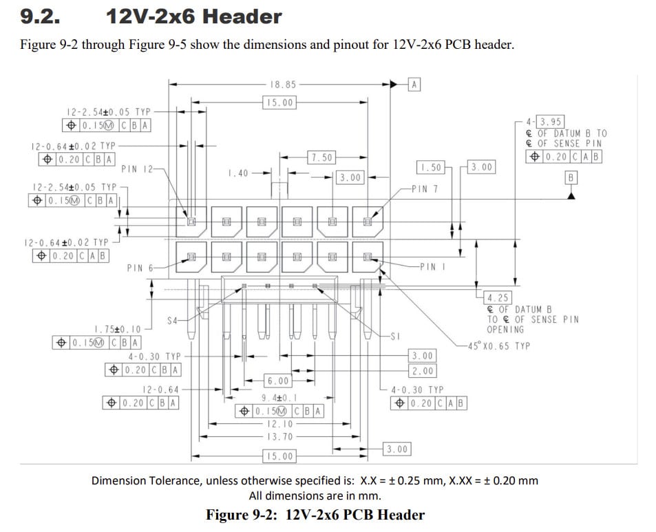
The total length of the connector’s housing is 6.6mm in both headers, but in the 12VHPWR header, the 12x power pins are 4.2mm long, while in 12V-2×6, the corresponding length is 4.45mm.
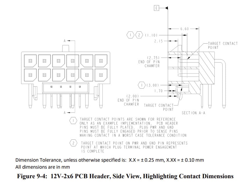
A piece of essential information on the schemes above is the “target contact point,” which represents the point at which power engagement is complete for both power and ground pins. In plain words, if the plug’s female pins reach this point, you won’t have power delivery issues. The target contact point is the same for both connectors, at 2.75mm from the pin’s tip.
The significant difference is on the sense pins, which in 12VHPWR are 4mm long, while in 12V-2×6 header are 2.75mm long since the space from the header’s edge was increased from 0.45mm to 1.7mm. The contact point remains the same at 3mm from the header’s edge to retain compatibility. Making the sense pins shorter ensures that the power and ground pins are correctly inserted before the GPU “senses” the sense pins. While the sense pins are not “sensed,” the GPU’s power limit is minimized; hence, there can be no power delivery issues.
This was a straightforward fix, which unfortunately doomed 12VHPWR. You make the sense pins shorter and implement the open-open = 0 Watts scenario, ensuring that only if the power and ground pins are inserted up to the contact point will the GPU start to receive power from the PSU. This way, you ensure that resistance on the corresponding wires is low and operating temperatures are the same.
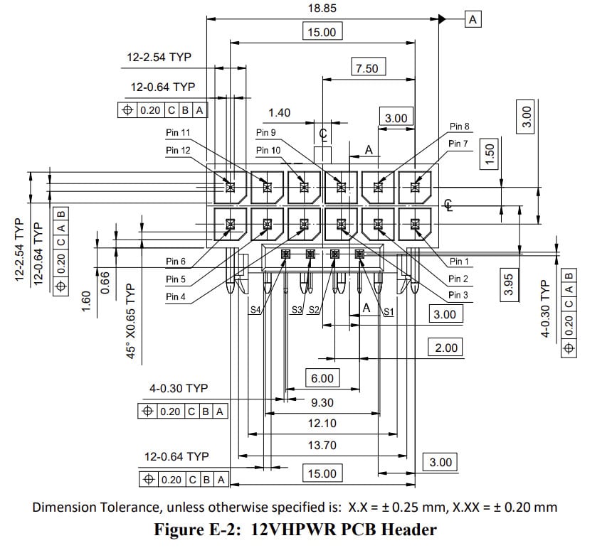
There are almost no differences here. The only difference I spotted is the length from S1 to S4, which in 12VHPWR is set at 9.3mm, while in 12V-2×6, it is 9.4+-1mm. There is also a minor change in the height of the sense pins plug, which, from 1.6mm in 12VHPWR, is at 1.75+-0.1 in 12V-2×6.
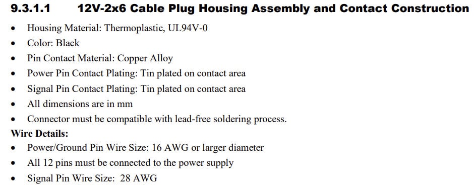
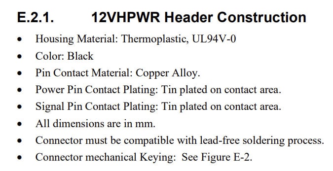
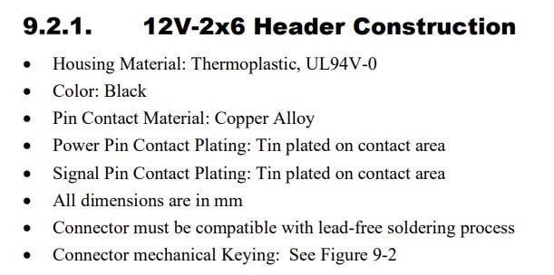
No differences here. What makes an impression is the color, which has to be black. The plug’s color doesn’t affect the header’s electrical characteristics, so I am not sure why only black color is allowed!
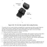
To ensure that cable bending won’t lead to problems. PCIe CEM 5.1 sets some new tests regarding side loading directions.
The key word here is Low-Level Contact Resistance, or LLCR. Suppose you bend the cables towards a direction. In that case, you might alter the resistance of the power and ground pins, and current loves to follow the paths offering the lowest resistance; hence, you will have unbalanced power distribution on the 12+4 pin plug and header, leading to overheating issues. Side loading is defined by PCIe CEM 5.1 as a load applied in each direction (right, left, top, downward) perpendicular to housing bodies.
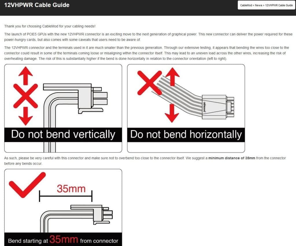
For example, when you install the high-power cable on your graphics card, you will probably have to bend it downward to lead it to the PSU. This is a guide by Cablemod, providing you with some info on how to bend their high-power cables to avoid issues. Although Cablemod says that 35mm from the plug’s end is fine, PCIe CEM 5.1 states that LLCR measurements should be conducted at 50mm from where the wire exists in the plug’s body, but in all directions! The side load should be 20N, and testers should perform 30 mating cycles between the connector and the cable assembly. LLCR should not vary on any pin more than 50% from the average of that pin’s respective group in each test condition. Lastly, the maximum LLCR permitted is 6 mOhm per contact. Anything above that can be dangerous.
Frequently Asked Questions
I have an ATX v3.0 PSU with 12VHPWR. Can I use the new 12V-2×6 cable?
There is no difference in the provided cables. The change is on the PCB header, so the cable you have now is practically the same as the ATX v3.1 PSUs. I repeat the difference is on the PCB headers only, both your PSU and the new generation of GPUs compatible with PCIe CEM 5.1, and on the open-open sense scenario, which ATX v3.0 PSUs don’t send.
I bought an ATX v3.1 PSU, but my graphics card uses the previous PCB header, 12VHPWR.
You will only have enhanced protection from the PSU side since your PSU has a 12V-2×6 PCB header. Nonetheless, the issues from melted connectors on the PSU modular boards were restricted. What you care about most is the PCB header on the GPU, and from the moment it is 12VHPWR, you won’t have the enhanced protection features that 12V-2×6 provides, sorry!
Are graphics cards with 12VHPWR connectors able to recognize the new “Sense” scenarios for Zero Watt Input?
They could do that through a BIOS update, but from the moment they use the older 12+4 pin header, it wouldn’t make much sense anyway.
My PSU uses a 2x 8-pin to 12+4-pin plug. Can it be ATX v3.1 if I change the cable?
You DON’T need to change the cable! Remember what I told you already? The difference is on the PCB header, not on the cable. Some brands, including Corsair and Super Flower, were smart enough to do it like that to claim ATX v3.1 compatibility without any significant changes. They need to implement, though, the corresponding circuit inside the PSUs to send the updated Sense scenarios, including, of course, the Zero Watt one. Otherwise, the protection features won’t be complete. Moreover, the cable plugs have to have the “H++” mark! They can also change the bulk cap to a smaller one and save money since ATX v3.1 is looser than ATX v3.0 regarding the hold-up time!
Are PSUs that use 2x 8-pin to feed the high power cable ATX v3.0 or/and ATX v3.1 compliant?
Yes, they are! According to the Intel ATX spec:
The two mating components of the 12V-2×6 are the Cable Plug, which terminates the cable harness, and the PCB Header, which is mounted on the Add-in Card and, OPTIONALLY, within a modular power supply.
So, Intel clarifies that the 12+4 pin PCB header on the PSU’s modular board is optional!
What do I need to get the complete protection that 12V-2×6 offers?
An ATX v3.1 PSU with a high-power (12+4 pin) cable plug and a graphics card with a 12V-2×6 PCB header. Since both are safe, you should not care whether the PSU uses a 12V-2×6 header or 2x-8pin sockets. The new micro-fit connectors occupy less space on the PSU’s modular board, so I assume that all manufacturers and brands should adopt them at some point.

Hello!
I have an ATX12 PSU (EVGA 1200W P3) and recently bought a RTX 5090… Should I consider upgrading my PSU to an ATX3.1?
Thanks!
It would be ideal yes, to have native 12V-2×6 cable and do not rely on adaptors. If you can find a cable: 2x 8pin to 12V-2×6 for your PSU, you could try this also.
Currently the adaptor that comes with the card uses 4x 8pin to the 12V-2×6… would a cable that bas 2x8pin be more recommended? I was actually thinking of the BeQuiet Dark Power Pro 13 – 1300W, but I’ve read a lot of bad ‘exploding PSU’ comments on this PSU and got discorauged.
Hi
I bought an RTX 5090 vangaurd and a Corasair HX 1200i ATX 3.1. But the PSU has no native 12V-2×6 it usies 2x 8pin to 12V-2×6. Is it safe for me to use the cable provided by corsair? Will I get full protections? or Should I change my PSU to something with native 12V-2×6 cable?
the PSU has 2x native to 12V-2×6. It is the same if not better than native to native 12V-2×6
Hello, thank you very much for this extensive overview!
I have just one question. I’ve ordered a new build, with a Seasonic GX-1000 ATX 3.0, which has a 12VHPWR connector. For GPU, I’ve ordered a RTX 4080 super, which I believe has a 12v-2×6, although I’m not sure, we’ll see. Assuming it indeed has a 12v-2×6 connector on the PCB, should I connect it to the PSU via the 12+4 -> 12+4 cable included with my PSU, or should I use the included 2×8-pin adapter I’ll receive with my GPU, to connect it to the PSU?
Hi! I would use the PSU’s native cable. Avoid the use of ANY adapters, please.
Well noted, that’s what I’ll do then. Thanks a lot for the prompt response.
Hi, quick question here. Im consodering a seasonic vertex gx-1200w white PSU for my next build. At my place it only costs 220 US dollars. I could also get a corsair rm1000x shift for the same price but i really like the cable sleeving on the vertex. It just looks 10times better.
Sorry for that long intro hahaha. The mal. Question is if I can use the atx 3.1 standart in the future when i use 2 of those 8pin connectors?
Instead of the 12vhpwr connector on the psu.
Hopefully you understand my question 🙂
In Korea, many people understand that pcie 5.1 is a socket on the graphics card of the main board. But in the content, we are all talking about power cables. Can I use pcie 5.0 as it is for the main board?
@crmaris Any idea when the new FSP ATX 3.1 line comes out? It’s been a while that they were announced.. any guess at all?
I will ask them! But from experience it will take them long enough to hit the stores.
im very new to this .
im going to upgrade my old 750w psu .
had a corsair hx1000 on the way but i canceled it because to me not having 12VHPWR header was not a true ATX3.0
so i bought a seasonic focus gx 1000 3.0.
i read this article but since English and psu are not my forte .
so a psu like a corsair rm1000e you said you can use 2×8 cable and all will be ok.
cant that be done aswell on a seasonic focus gx 1000 3.0 ?
has 12VHPWR header .
But has the 2×8 too.
Yes, the ATX v3.x spec ONLY requires the 12+4 pin header to be on the GPU and it is not required to be installed on the PSU, too. So PSUs with 2x 8pin are fine.
i had a corsair hx1000 coming and canceled it Since I saw had no 12VHPWR on the psu itself so no data transfer.
so just bought yesterday seasonic focus gx 1000 3.0
has the 12VHPWR .
so the corsair is ok using 2×8 to the new standard .
can it be done too on seasonic ?
Just using a 2×8 ..
One quick question:
If i buy for example a FSP Hydro Ti Pro which has a dedicated (old) 12 pin and 4 PCI-E 8 Pin sockets, will i be able to use the advantage of this new ATX 3.1 standard if i use a 2×8 pin to 12 pin cable rather than the 12 pin to 12 pin?
Hello !
“There is only one catch: ATX v3.0 PSUs don’t send the open-open signal when nothing is connected to their high-power plugs.”
This means that if I buy a Super Flower Leadex VII XG 1000W ATX the protection will be only on the GPU side and also the PSU won’t send the open-open signal since it’s not configured right? So to have the complete full protection except a newer GPU , also SuperFlower need to update their circuit inside the PSU to be able to send open-open signal? So it’s not completely ATX 3.1 compatible as advertised. It doesn’t offer the full benefits 🙁
This is not required and actually they do so please don’t pay attention to what I wrote back in the day. The only change in ATX v3.1 that matters is the new PCB header and the lower hold-up time.
I have a question about this statement:
“Some brands, including Corsair and Super Flower, were smart enough to do it like that to claim ATX v3.1 compatibility without any significant changes. They need to implement, though, the corresponding circuit inside the PSUs to send the updated Sense scenarios, including, of course, the Zero Watt one.”
If, for example, I buy a Corsair RM1000e (which has only 8-pin headers) and then later I buy a GPU with a 12V 2×6 header, will the PSU automatically be able to send the updated power delivery for sense scenarios? Or, does the PSU require some kind of physical adjustment to be able to interpret the new sense scenarios?
It is easier actually than a circuit. You just need to make some changes to the connector on the GPU’s side.
I have the same question as Alex, but I don’t understand your answer. I just bought a RM850x shift which have 2x8pins – will it support the 0w safety scenario if I buy a GPU with the 12v2x6?
I am trying to help my nephew choose a new PSU, but I am having difficulties understanding how the sense-features works, and don’t want to recommend the psu I bought if it essentially is obsolete for future graphics cards.
Yes, it will!
Hi, so all I really need to know I is that will a ATX v3.0 PSU with a 12VHPWR connector still be compatible with a future videocard that use’s a 12V-2×6 connector? As long as the ATX v3.0 PSU use’s a 12VHPWR connector to a 12V-2×6 adapter cable?
It will be compatible yes, there is no change to the cable.
So, just to be explicit, if I’m looking to buy new parts for a new build today (10/6/2023) – would any of the Asus or Corsair PSUs, along with any 4090 GPUs, be completely compatible with 3.1 on both ends?
So far there are no v3.1 PSUs