Part Analysis
| General Data | |
| Manufacturer (OEM) | CWT |
| Platform | CSA |
| PCB Type | Double-Sided |
| Primary Side | |
| Transient Filter | 4x Y caps, 2x X caps, 2x CM chokes, 1x MOV, 1x Power Integrations CAP200DG (X Capacitor Discharge IC) |
| Inrush Protection | NTC Thermistor SCK-207R0 (7 Ohm @ 25°C) & Relay |
| Bridge Rectifier |
GBU1506 (600V, 15A @ 100°C)
|
| APFC MOSFETs |
2x Way-On WML36N65C4 (650V, 20A @ 100°C, Rds(on): 0.097Ohm)
|
| APFC Boost Diode |
CRMicro CRXI08D065G2 (650V, 8A @ 165°C)
|
| Bulk Cap(s) |
Nichicon (400V, 680uF, 2000h @ 105°C, GL)
|
| Main Switchers |
4x Silan Microelectronics SVF20N50F (500V, 12.6A @ 100°C, Rds(on): 0.27Ohm)
|
| APFC Controller | Champion CM6500UNX |
| Resonant Controller |
Champion CM6901T6X
|
| Topology | Primary side: APFC, Full-Bridge & LLC Resonant Converter Secondary side: [12V] Synchronous Rectification & [Minor Rails] DC-DC converters |
| Secondary Side | |
| +12V MOSFETs | 6x PingWei PWC013N04ES (40V, 155A @ 100°C, Rds(on): 1.3mOhm) |
| 5V & 3.3V | DC-DC Converters: 4x UBIQ Semi QM3054M6 (30V, 61A @ 100°C, Rds(on): 4.8mOhm) PWM Controller(s): ANPEC APW7159C |
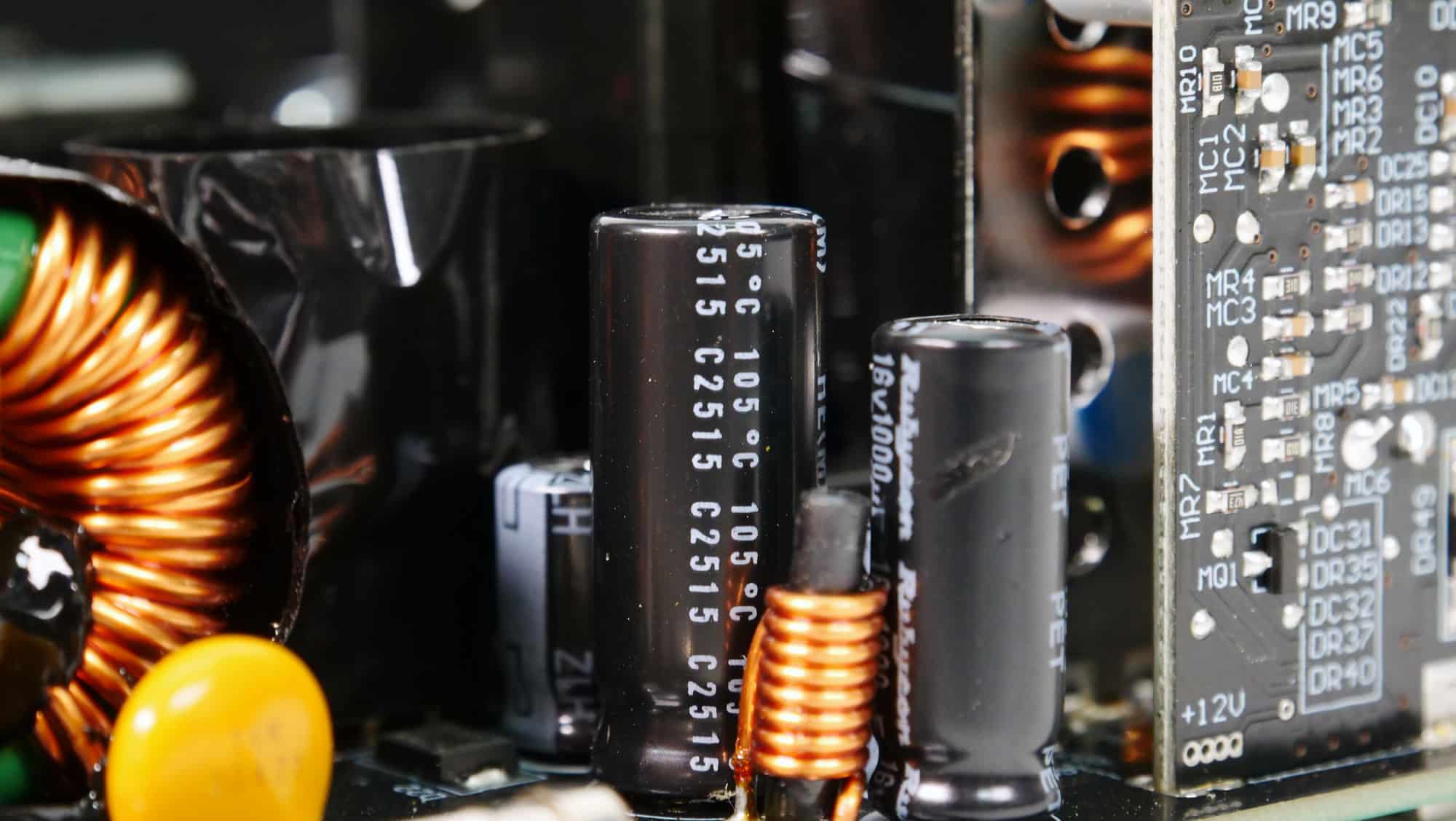
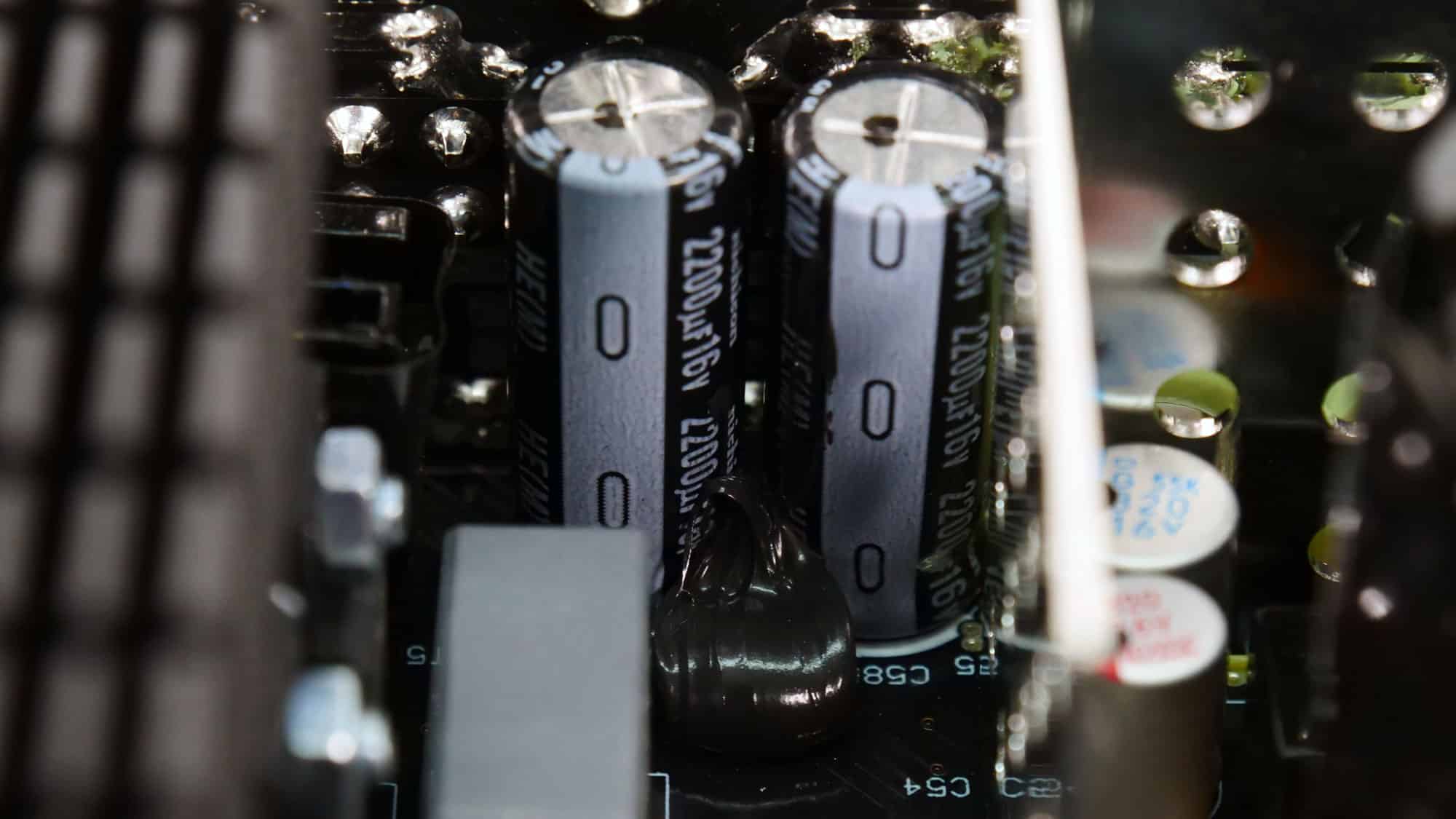
| Filtering Capacitors | Electrolytic: 2x Nippon Chemi-Con (@ 105°C, W) 3x Nichicon (4-10,000 @ 105°C, HE(M)) 3x Rubycon (6-10,000 @ 105°C, ZLH) 2x Rubycon (4-10,000 @ 105°C, YXF) Rubycon (4-10,000 @ 105°C, YXJ) Polymer: 13x Nippon Chemi-Con, 11x FPCAP, 2x no info |
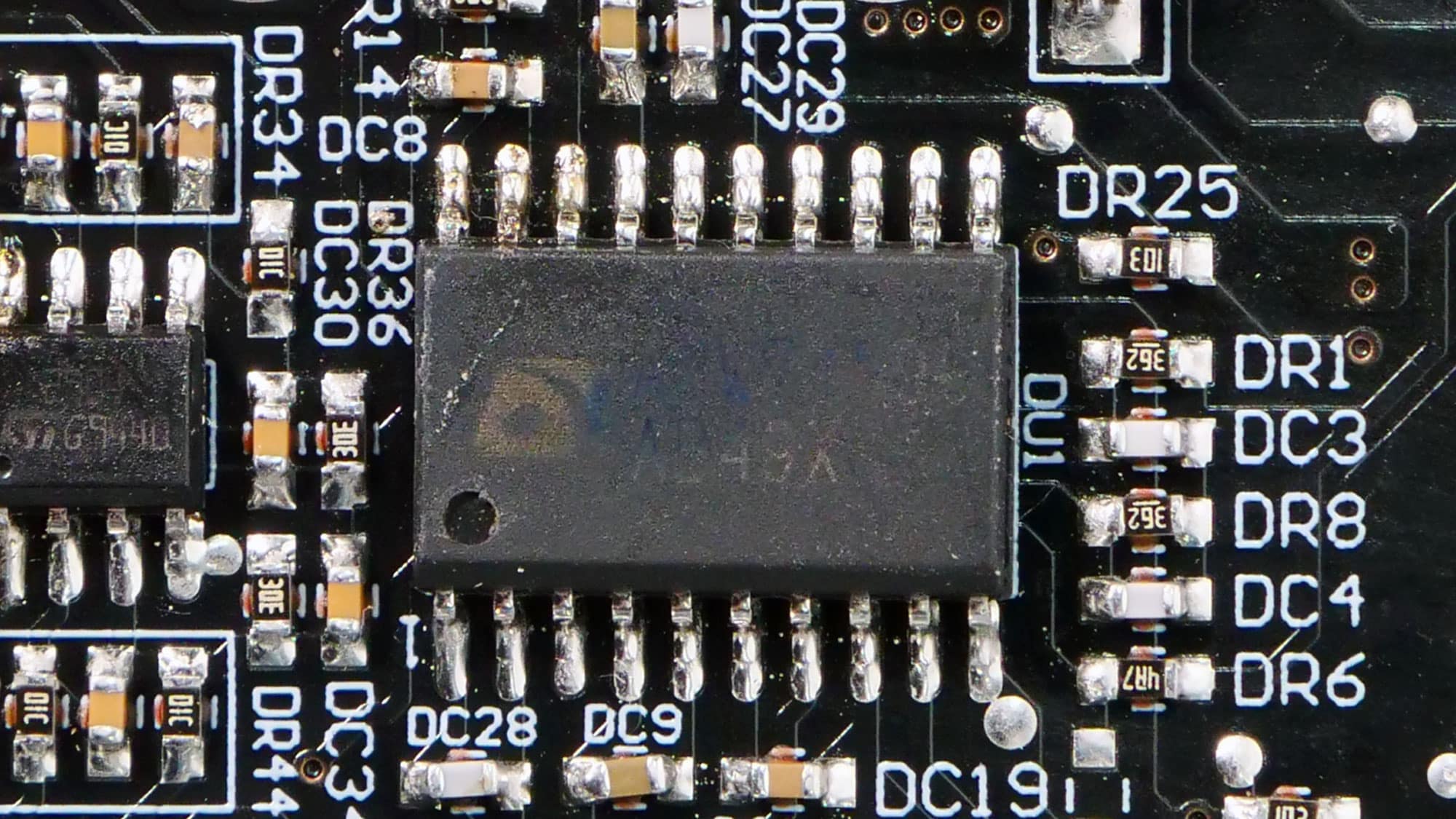
| Supervisor IC | NDP NDP8313iKC |
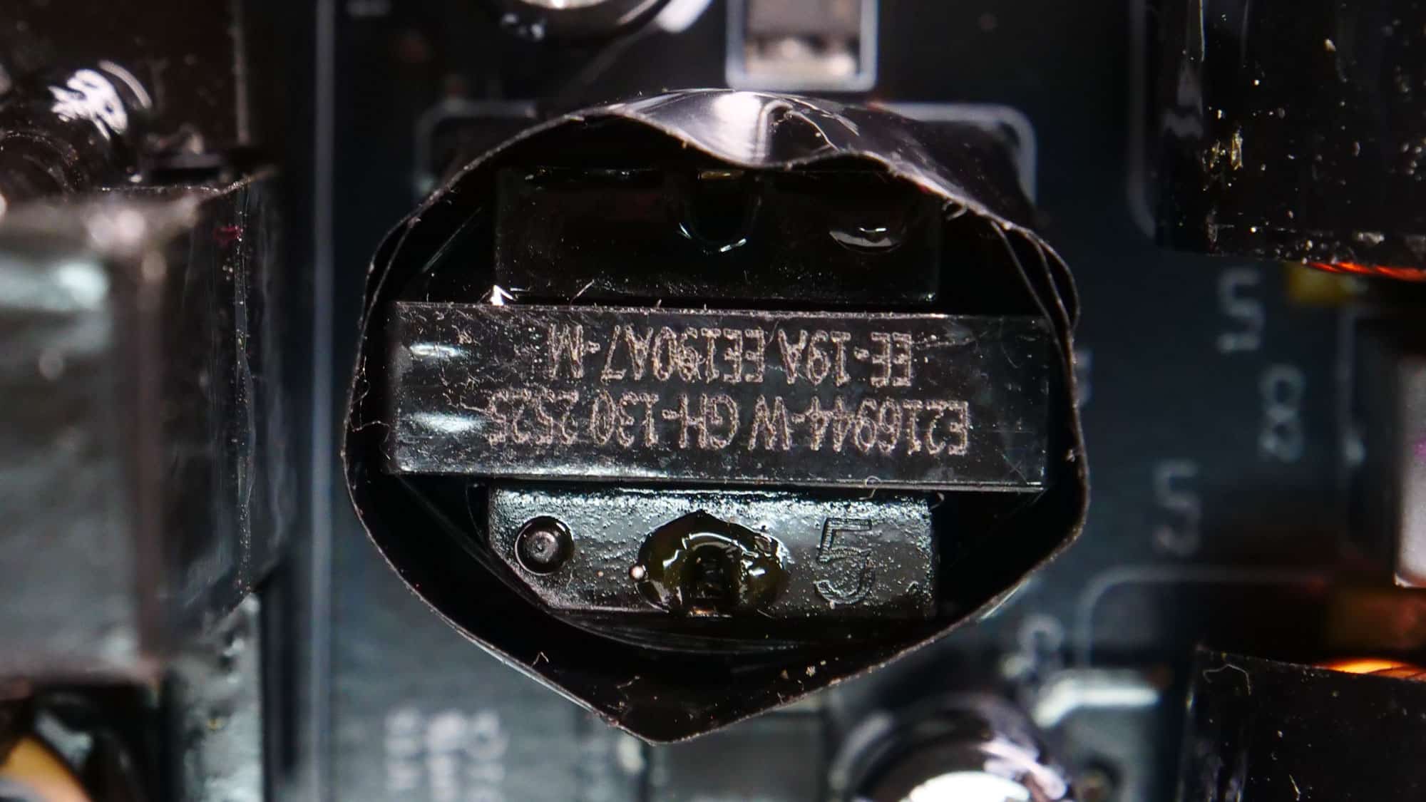
| Fan Model | TT-13525 CWT13525H12F-9 (135mm, 12V, 0.4A, Fluid Dynamic Bearing Fan) |
| 5VSB Circuit | |
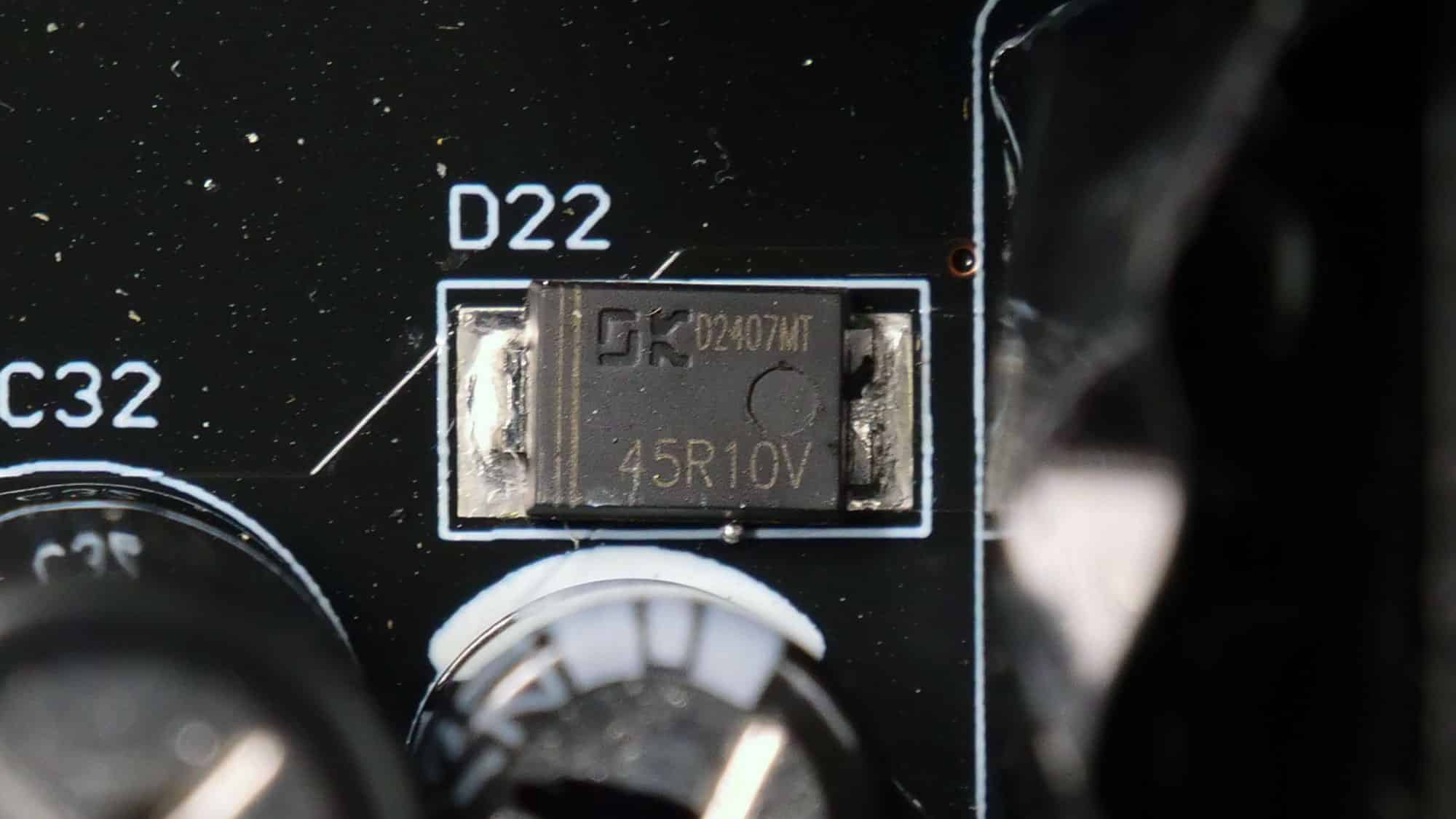
| Rectifier (High Side) |
Dongke DK5V45R10V (45V, 10mOhm)
|
| Standby PWM Controller | |
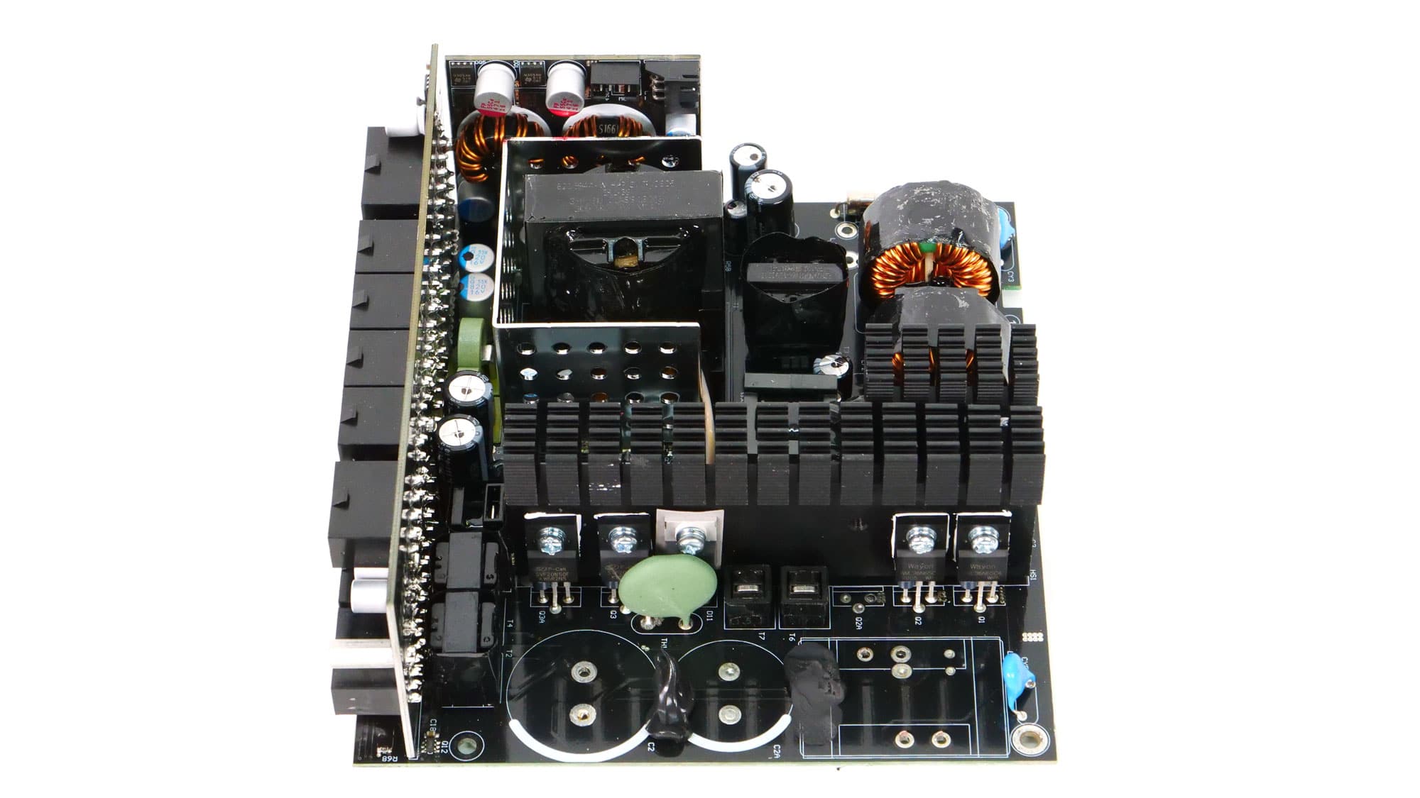
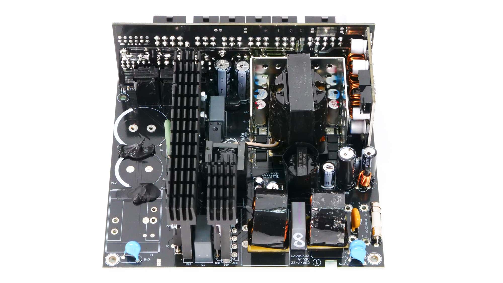
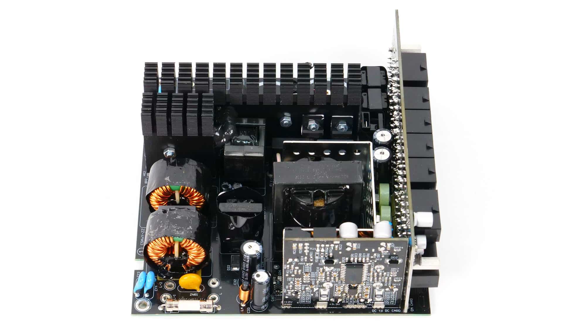
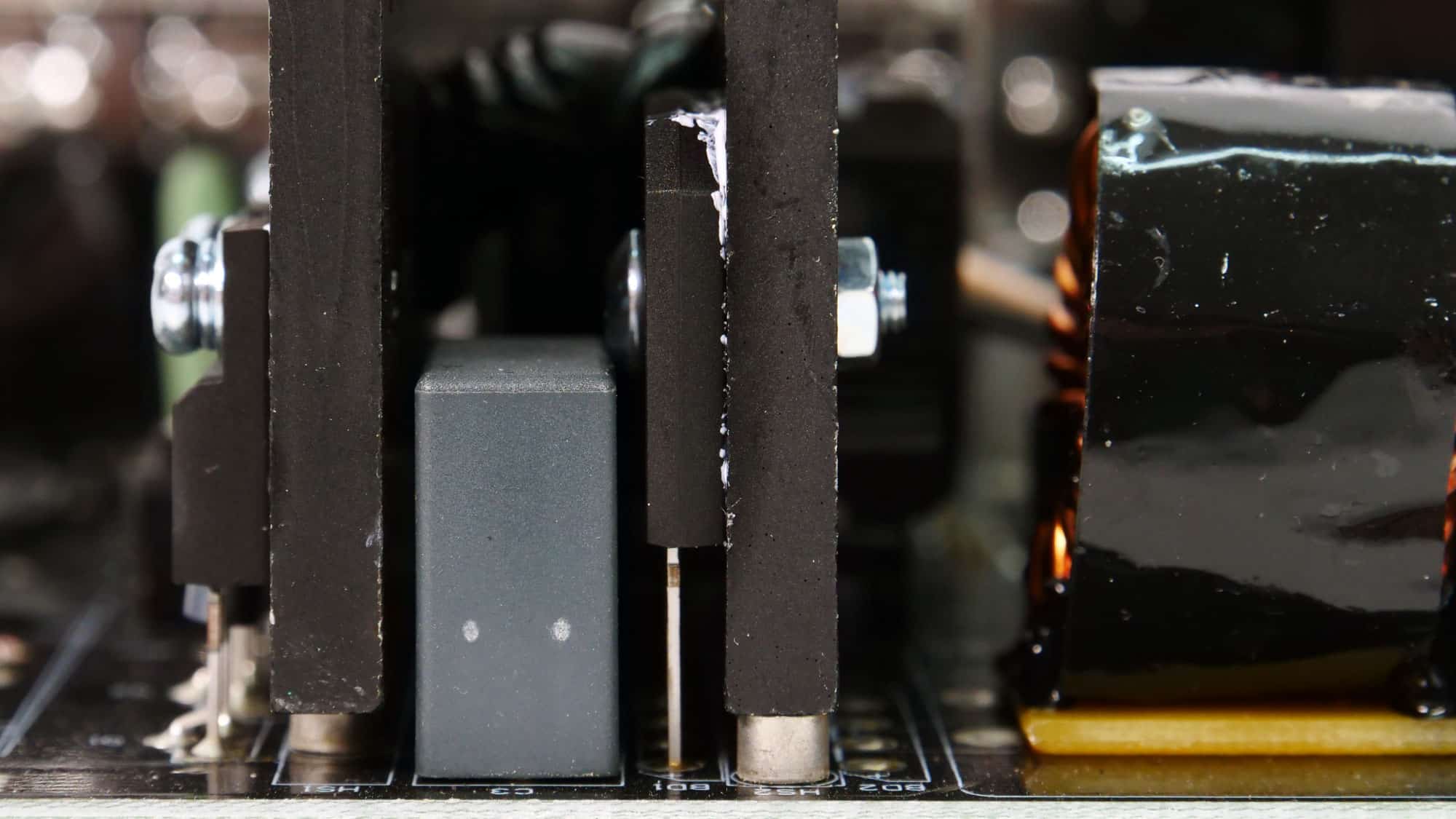
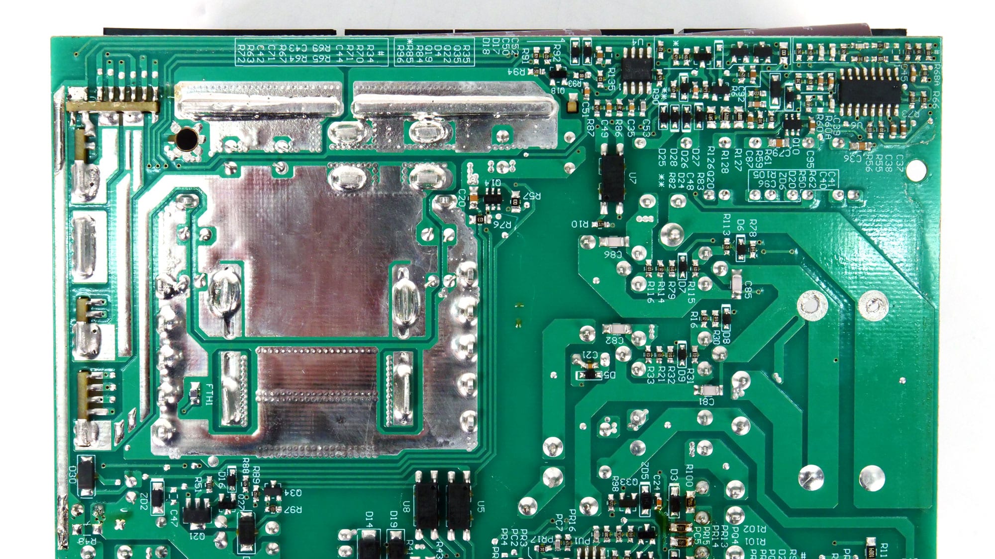
This is the same platform used in the PT 1200 and PT 1000 models, with some component changes due to the lower maximum power output. CWT supplies the platform, which features a modern design with a full-bridge topology on the primary side, paired with an LLC resonant converter to minimize energy losses. The PCB is compact, so to maintain cooling without pushing the fan too hard, CWT equipped the primary side with large heatsinks. As is typical for CWT designs, the secondary side uses much smaller heatsinks—essentially a metal plate surrounding three sides of the main transformer, serving both as a cooling aid and a common-mode EMI shield. The transformer’s aluminum cover also provides limited high-frequency magnetic shielding.
To keep costs down, CWT opted for Chinese-made FETs rather than premium brands such as Infineon or Vishay. However, it didn’t cut corners on electrolytic capacitors, opting for reputable, high-quality brands. Interestingly, CWT also manufactures the cooling fan in-house rather than sourcing it from another supplier—a smart and strategic decision.
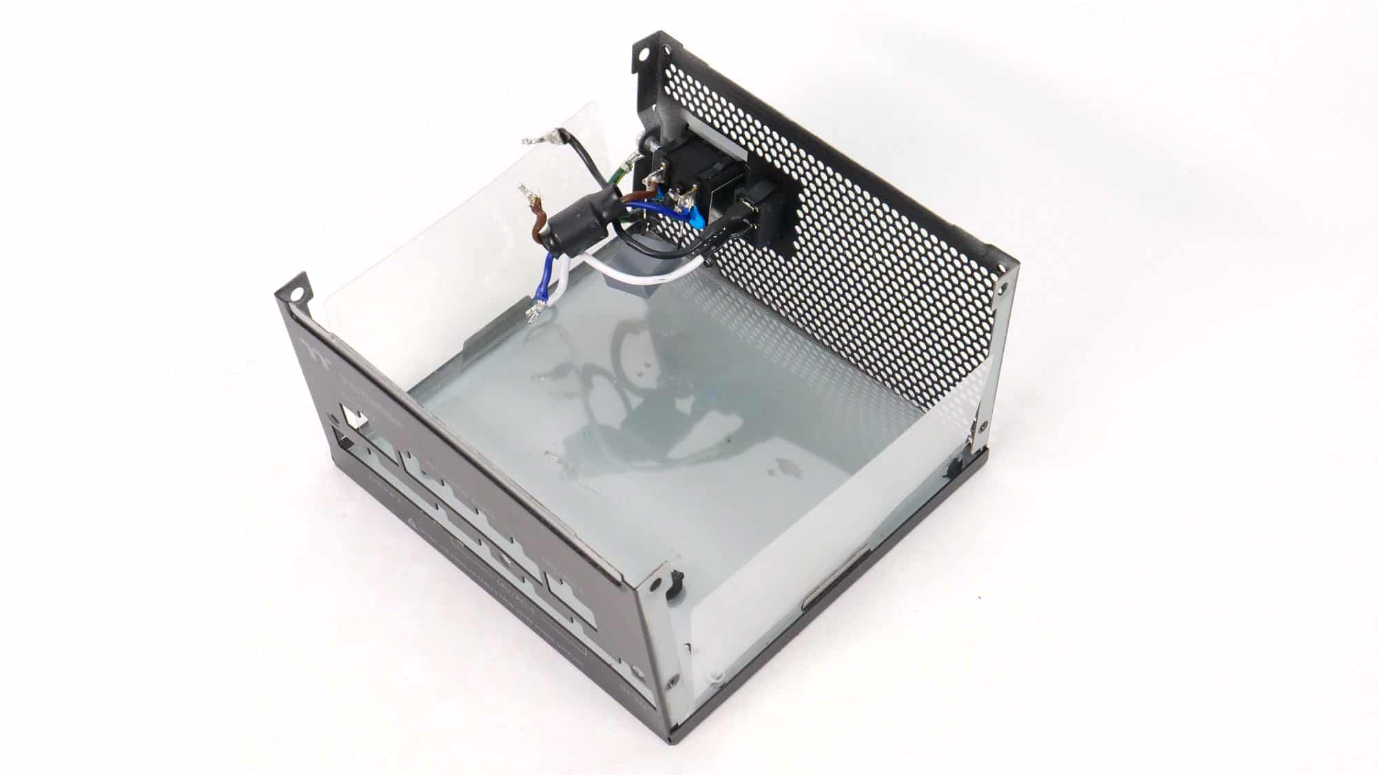
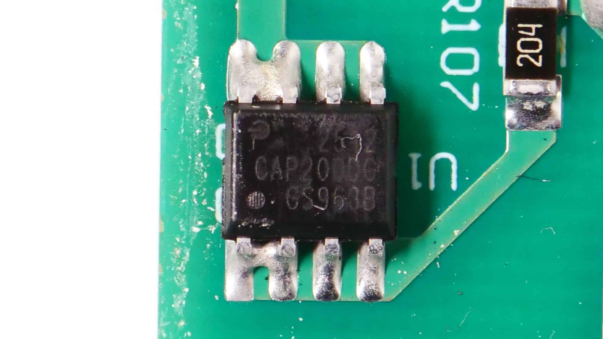
The transient filtering stage contains all the necessary components to block both incoming and outgoing EMI emissions. Typically, it starts at the AC receptacle and continues on the main PCB. It also includes a discharge IC for its X caps to provide a slight efficiency boost.
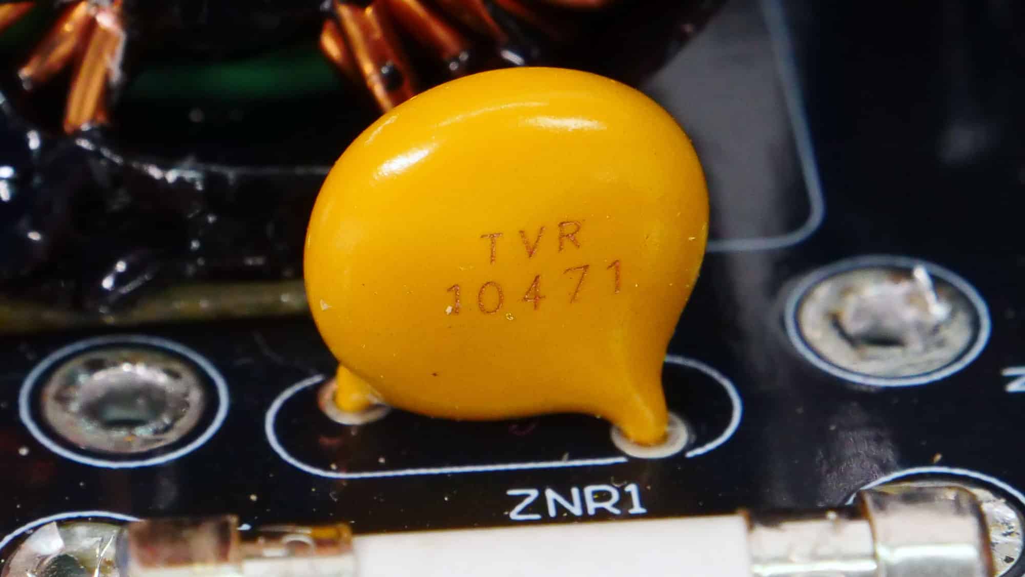
There is an MOV to protect from voltage surges and an NTC thermistor with a resistance of 7 ohms. Moreover, a bypass relay supports the NTC thermistor.
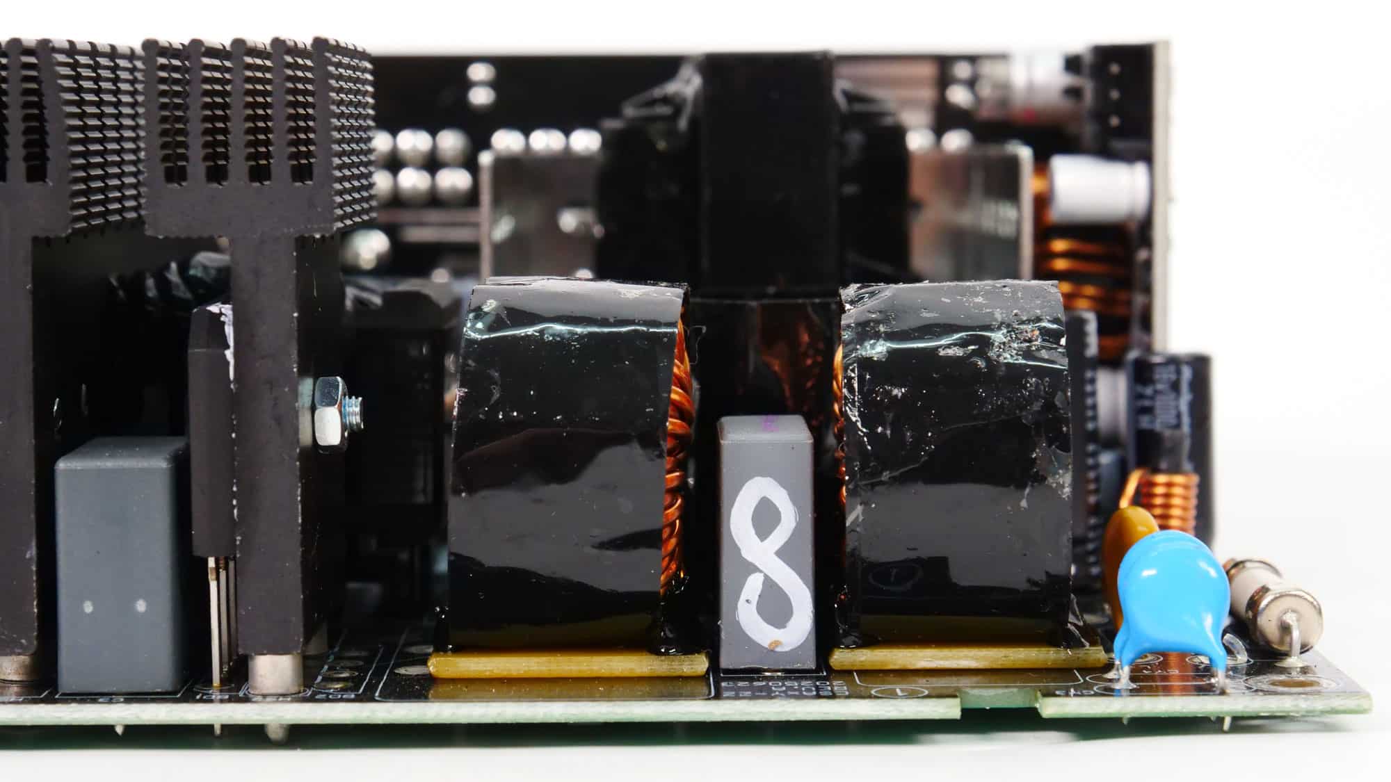
A single bridge rectifier converts the incoming AC signal to a loosely regulated DC voltage. It can handle up to 15A. I cannot say that I like seeing this lonely X cap so close to the bridge rectifier and to the primary heatsink, since both can get pretty hot.
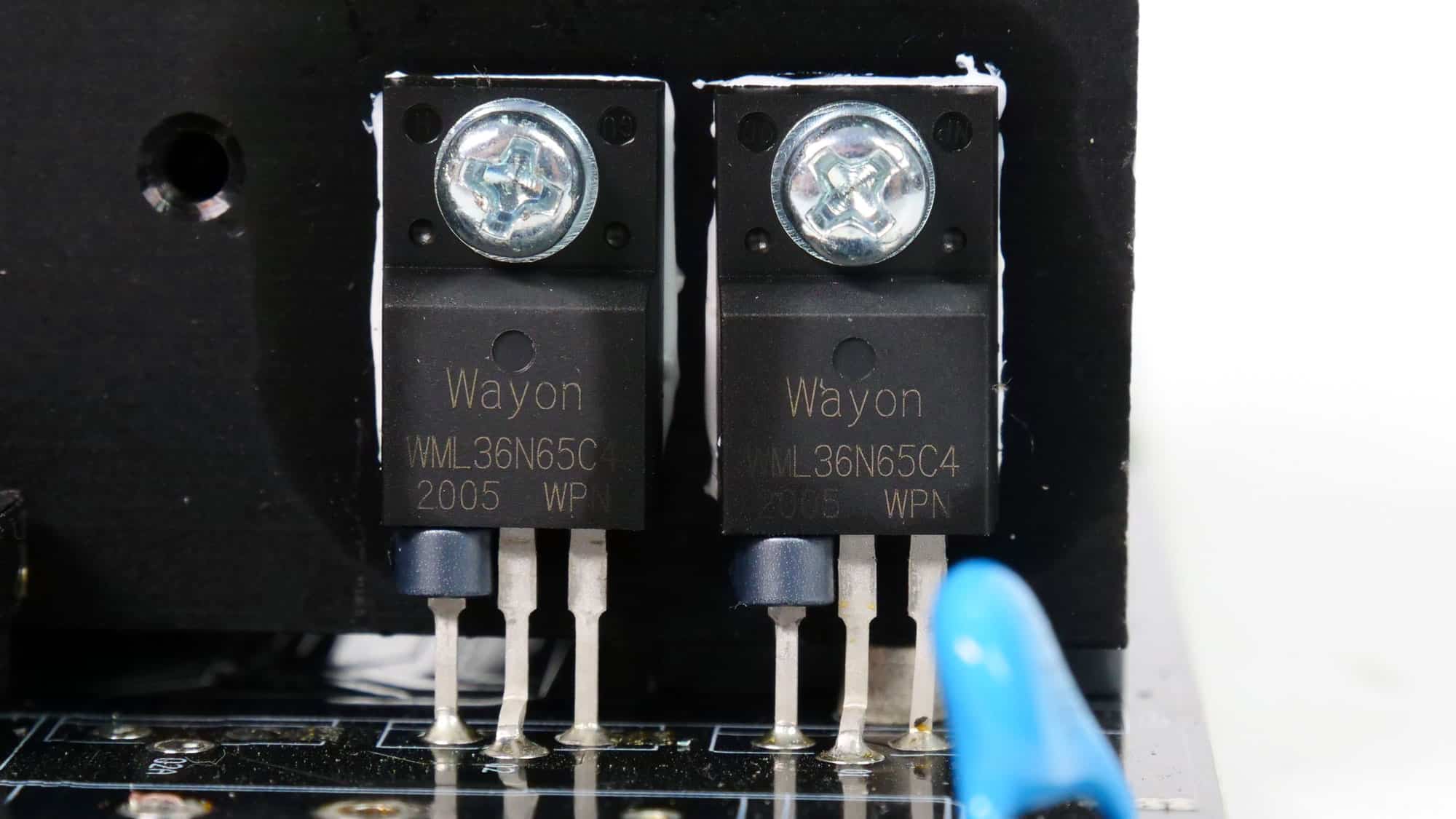
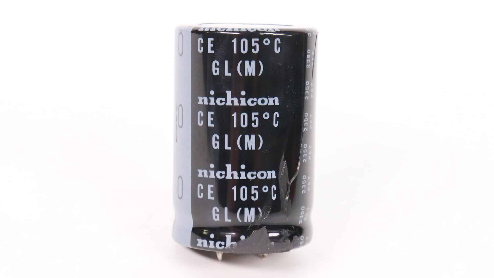

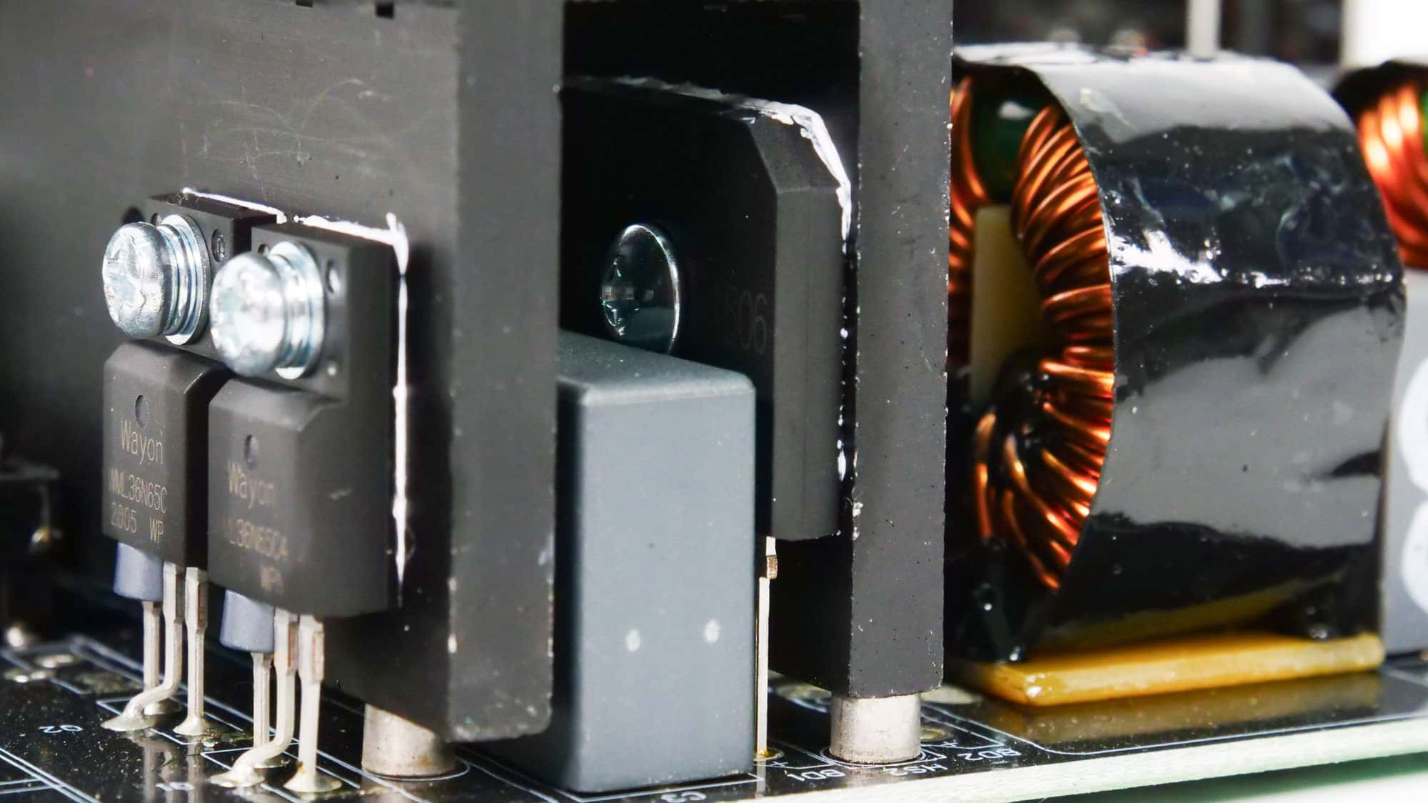
The APFC converter uses two Way-On WML36N65C4 FETs and a single CRMicro CRXI08D065G2 boost diode. Nichicon manufactures the bulk capacitor. Its capacity is 680 μF, and both are rated for 2,000 hours at 105 °C. The voltage rating is 400V, which is pretty close to the APFC’s DC bus voltage (approximately 380-400V DC). It would be better to use 420V-rated bulk caps or ideally 450V.
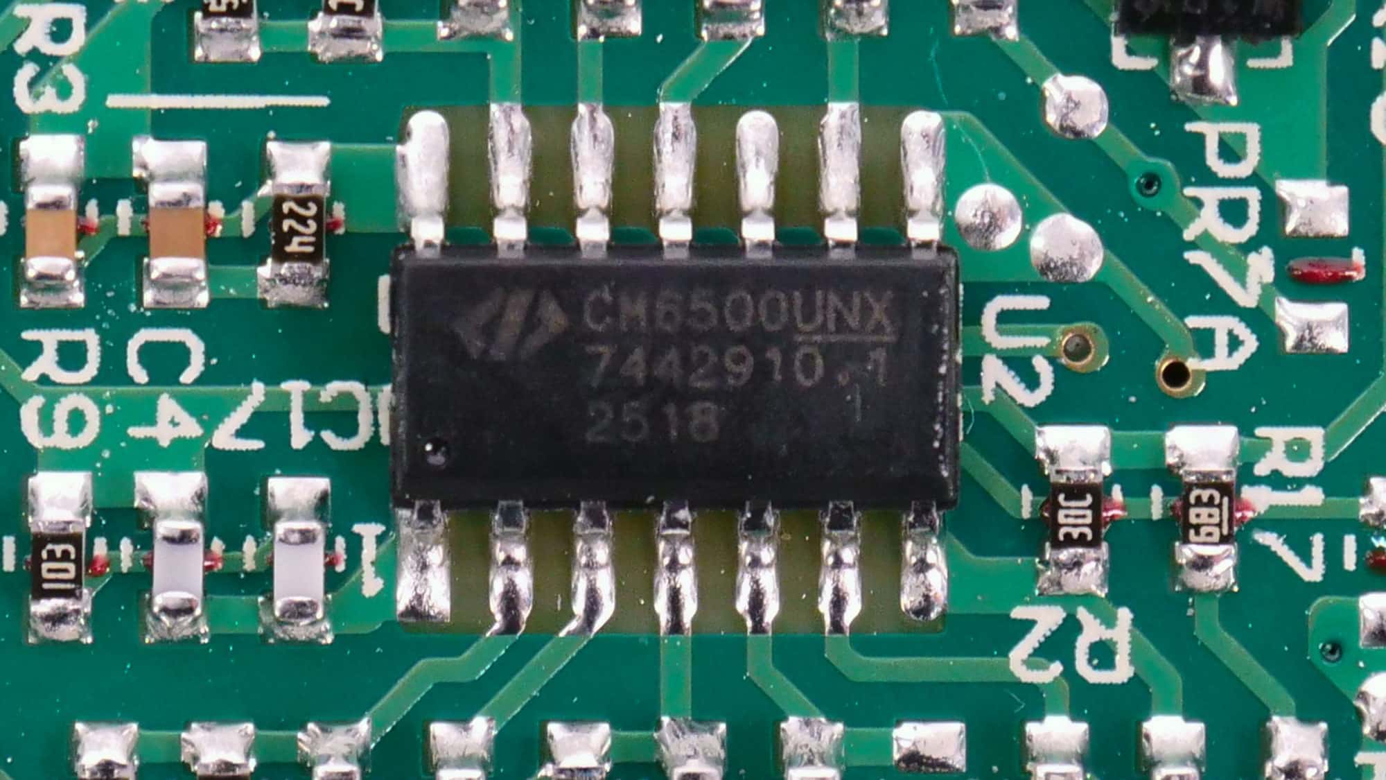
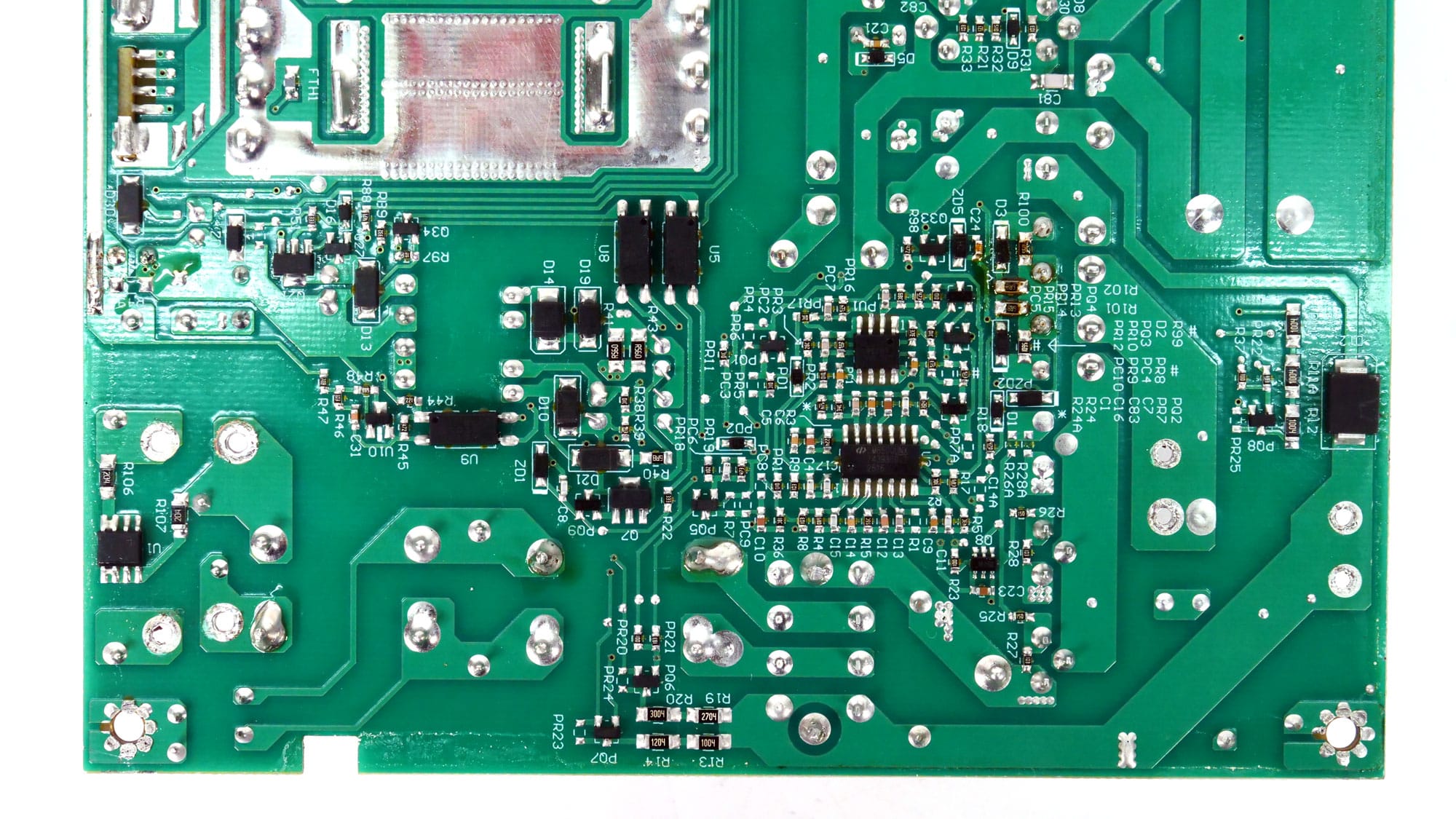
The APFC controller is a Champion CM6500UNX.
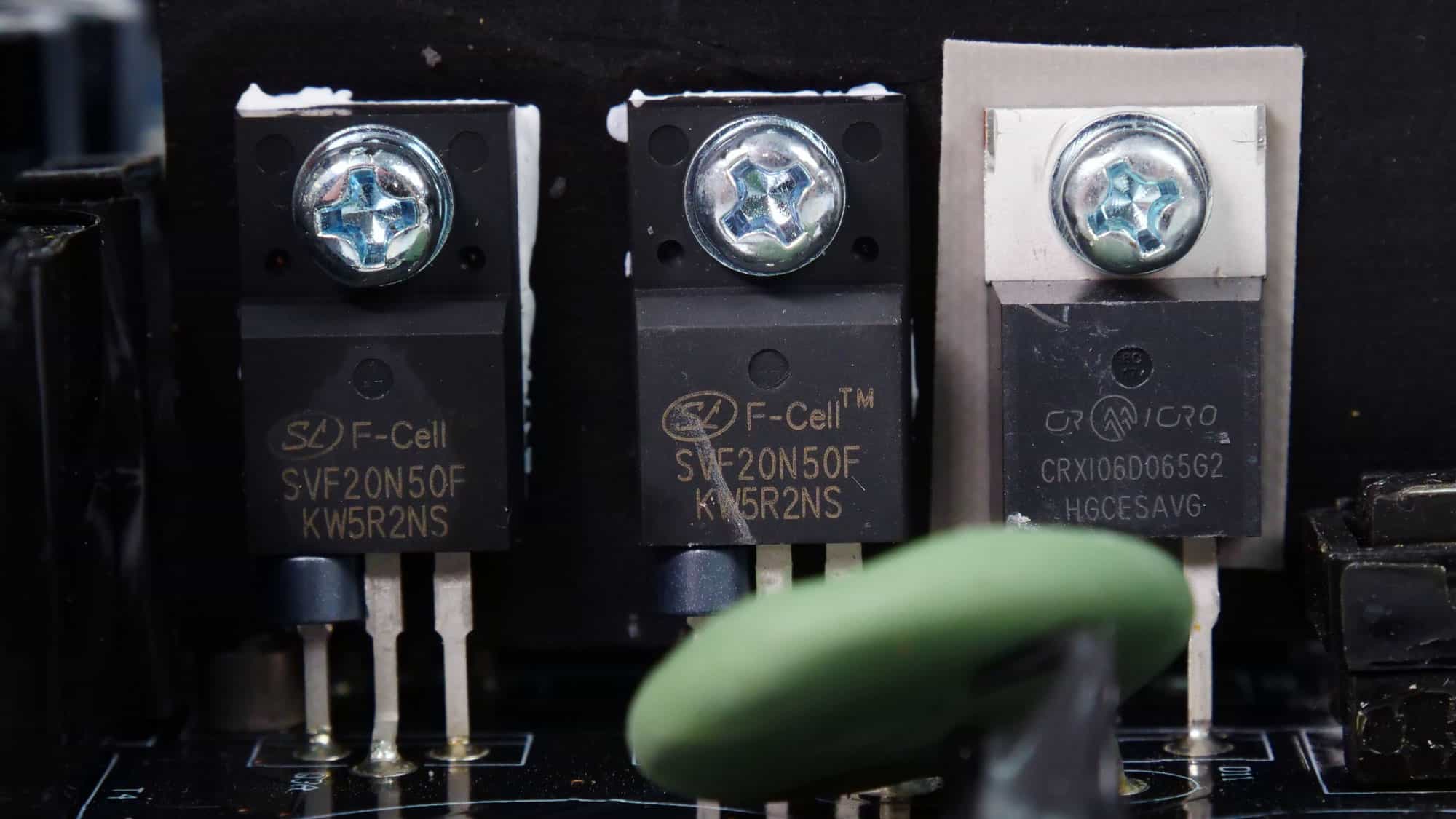
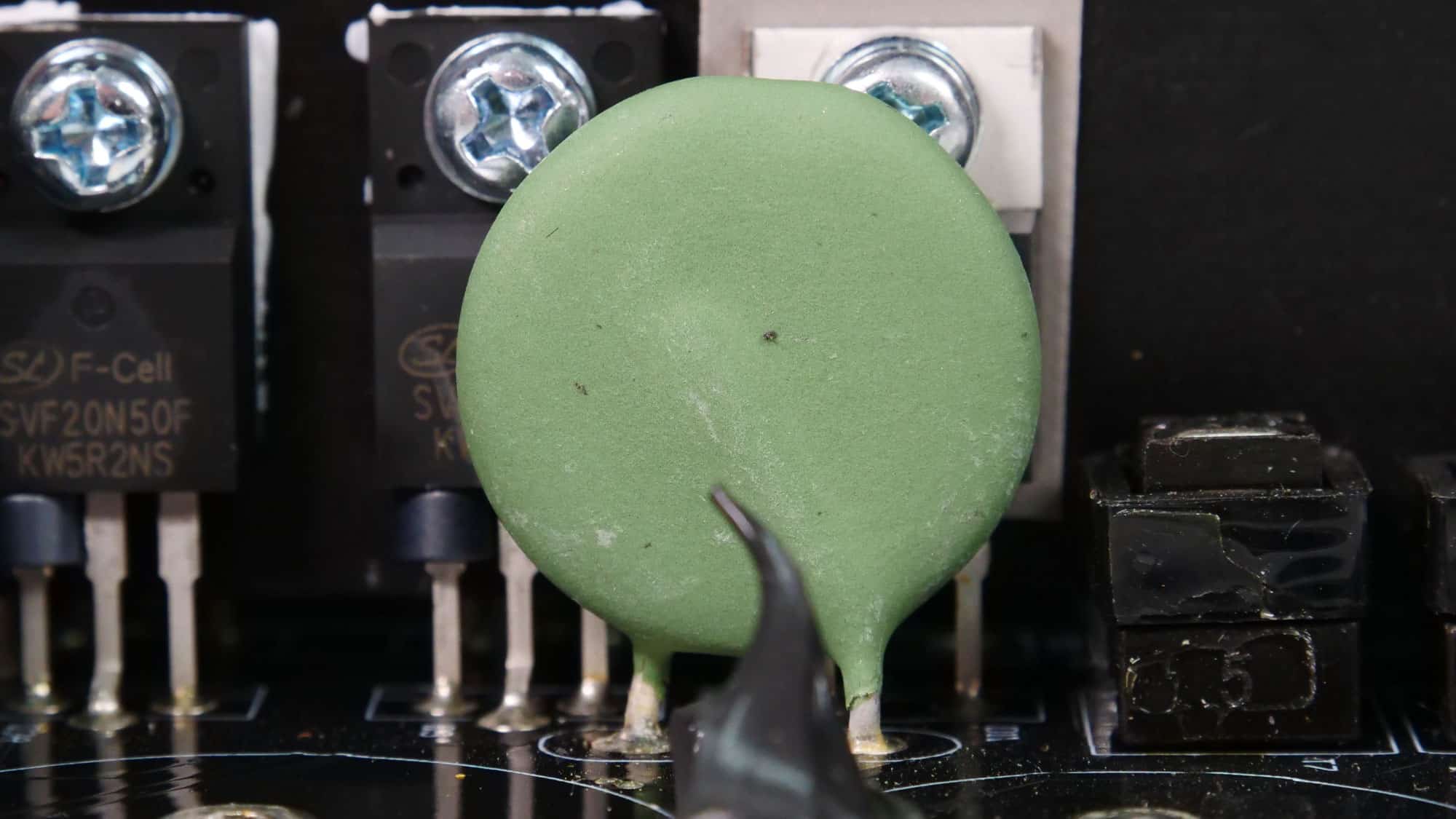
Four Silan Microelectronics SVF20N50F primary-switching FETs are used in a full-bridge topology, and an LLC resonant converter is employed for enhanced efficiency.
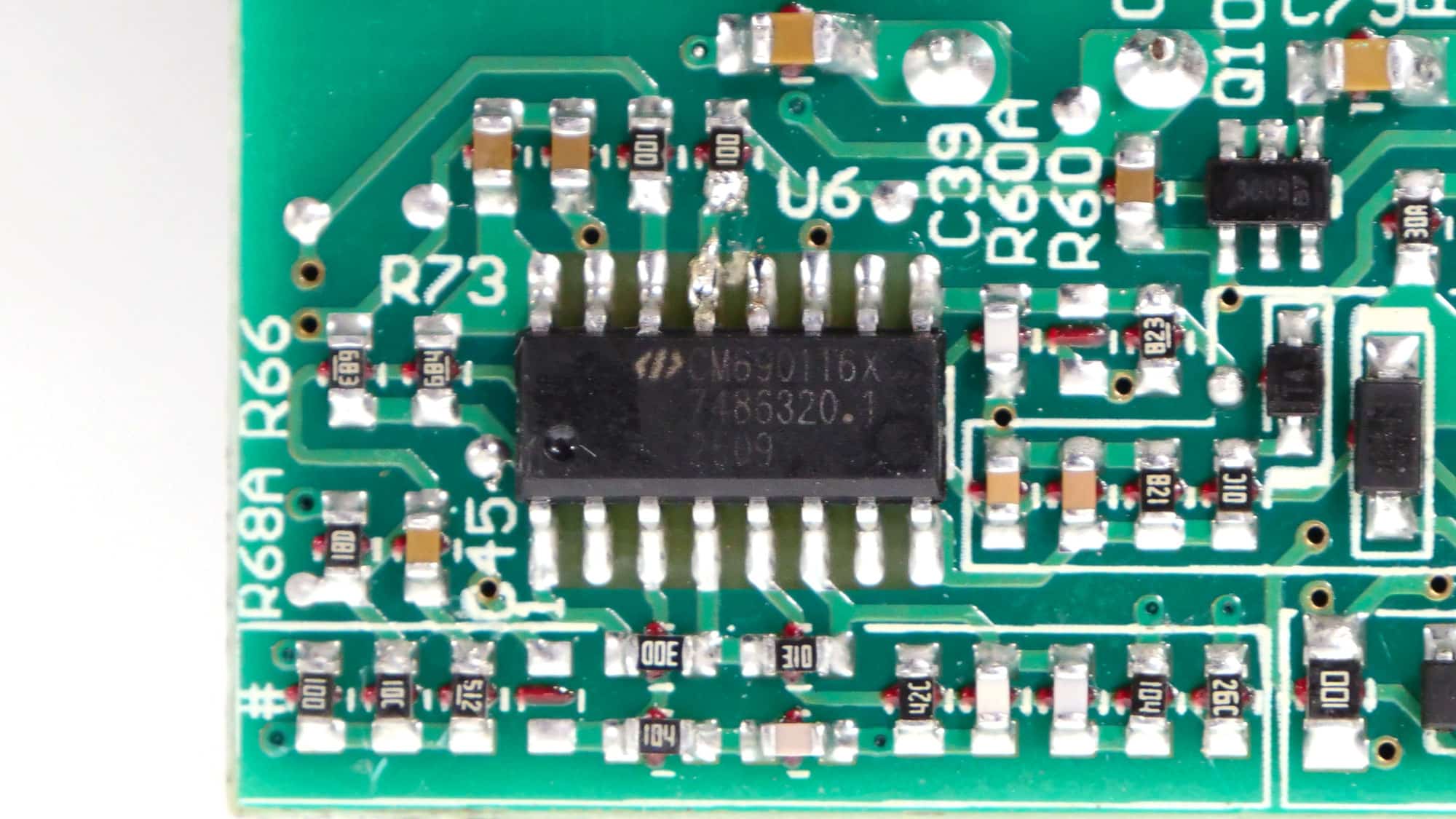
The LLC resonant controller is a Champion CM6901T6X.
![]()
The PSU’s main transformer. One of its main functions is to electrically isolate the primary and secondary sides.
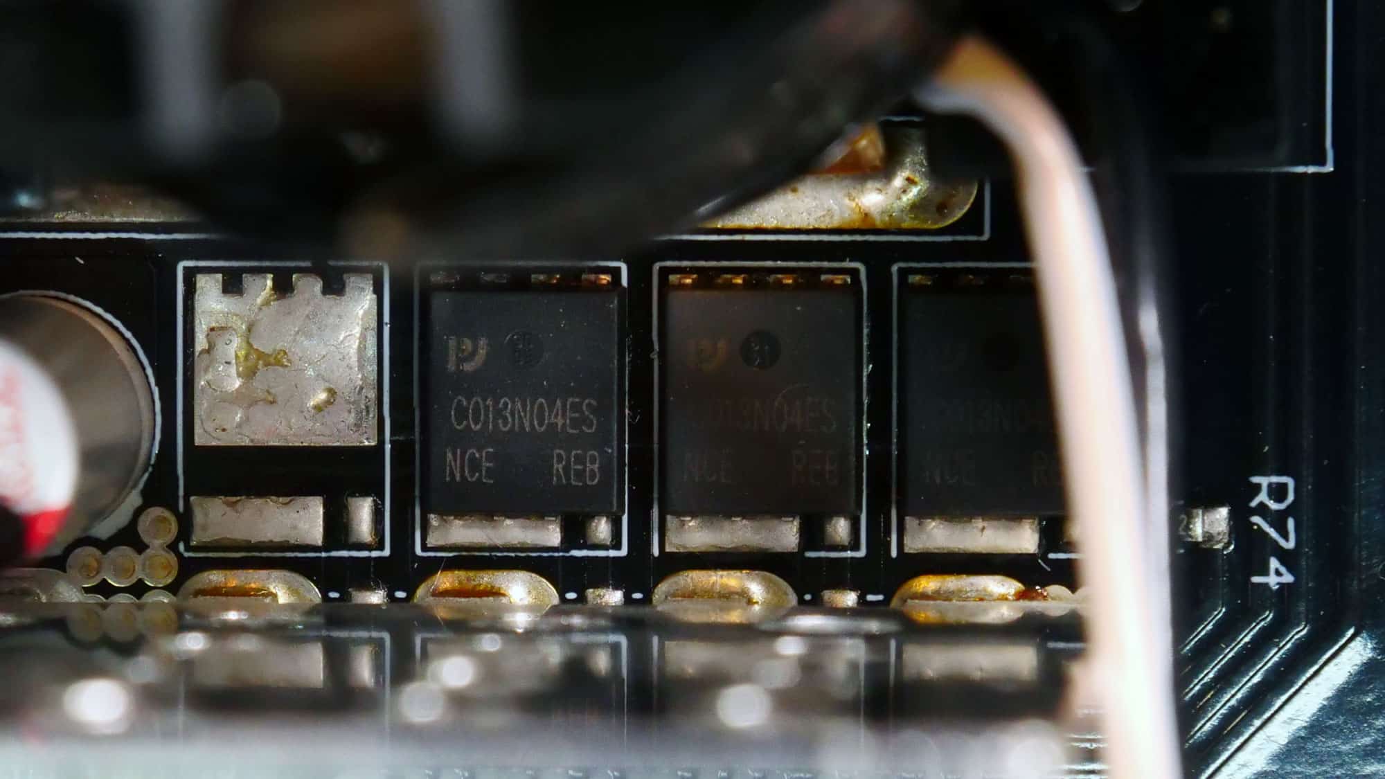
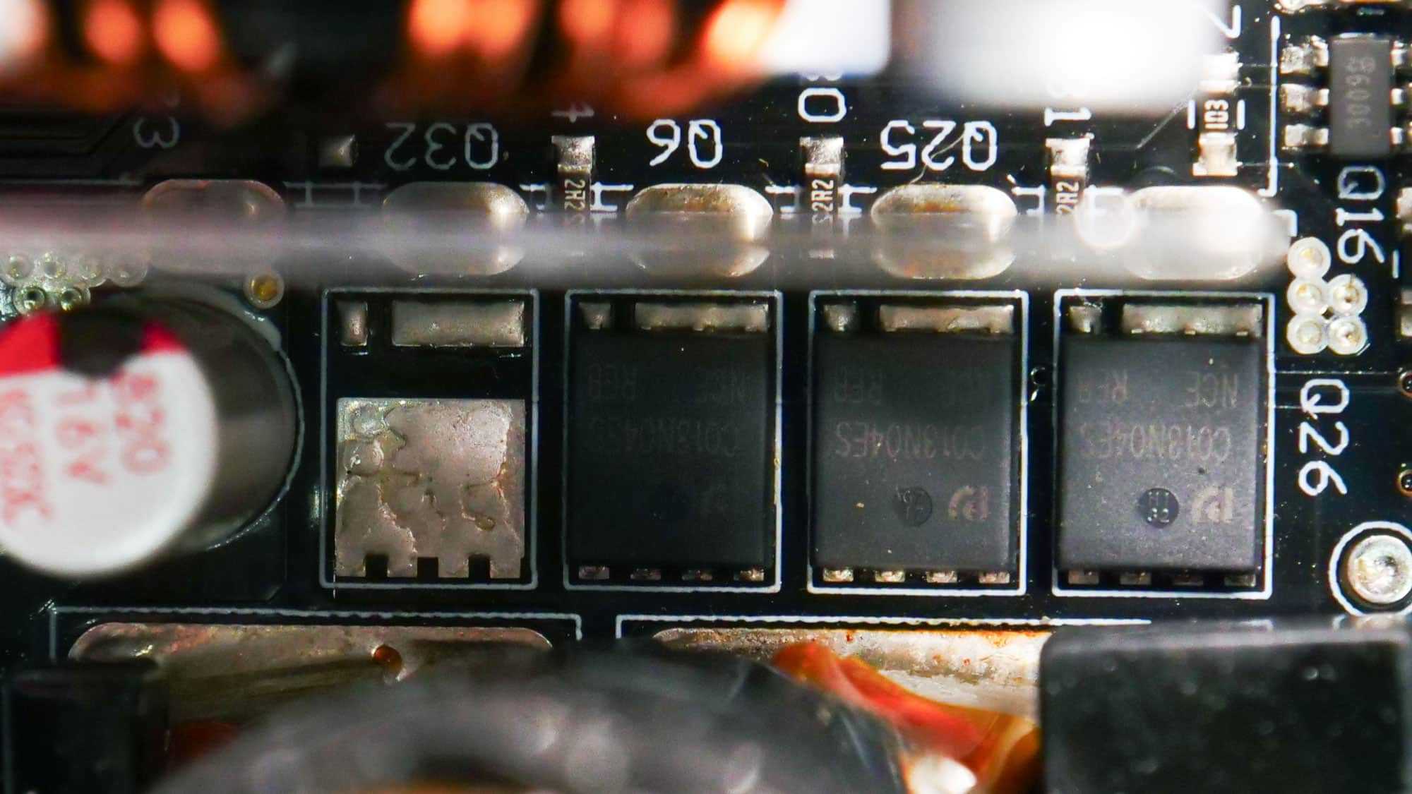
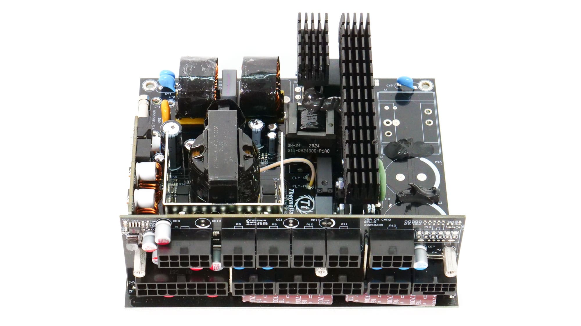
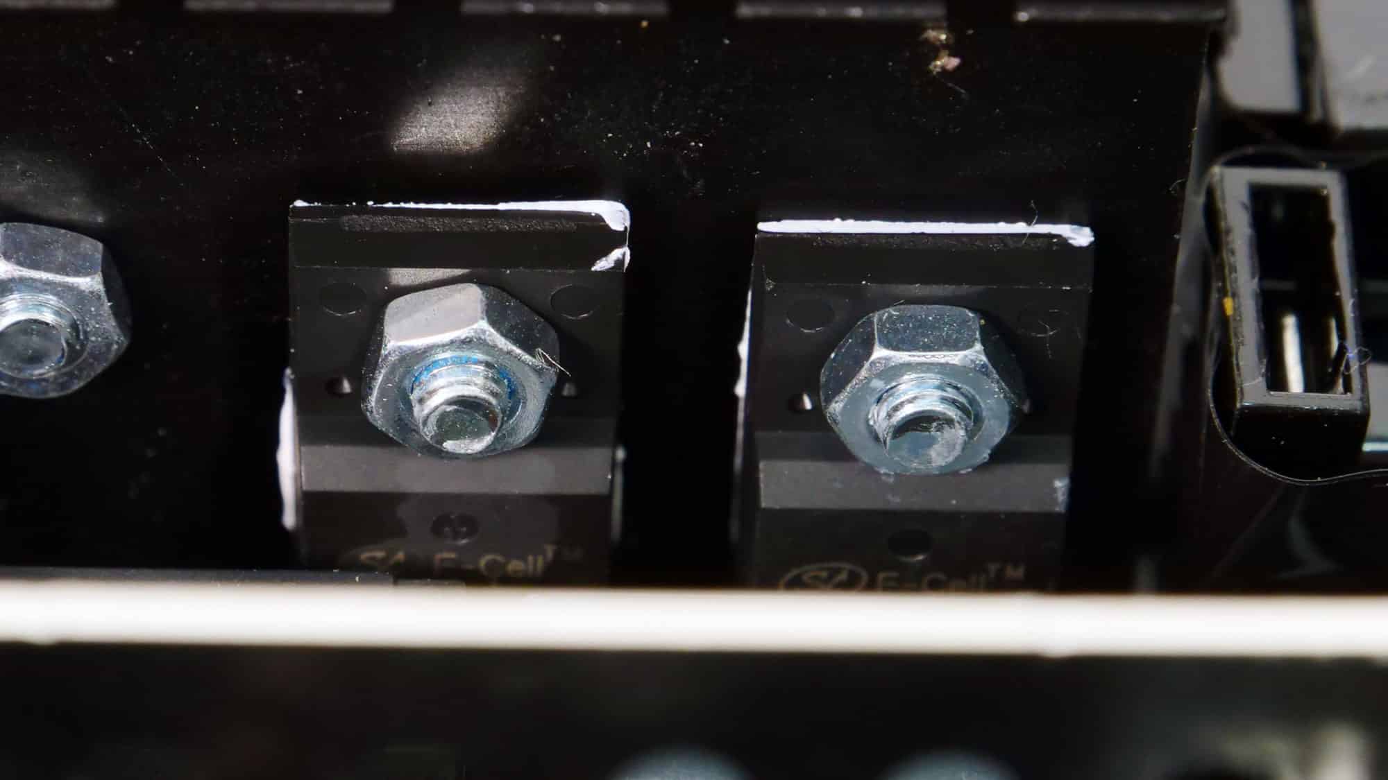
Six PingWei PWC013N04ES FETs regulate the 12V rail. They are installed on the business (top) side of the PCB. Eight of the same type of FETs are installed in the 1000 and 1200W models.
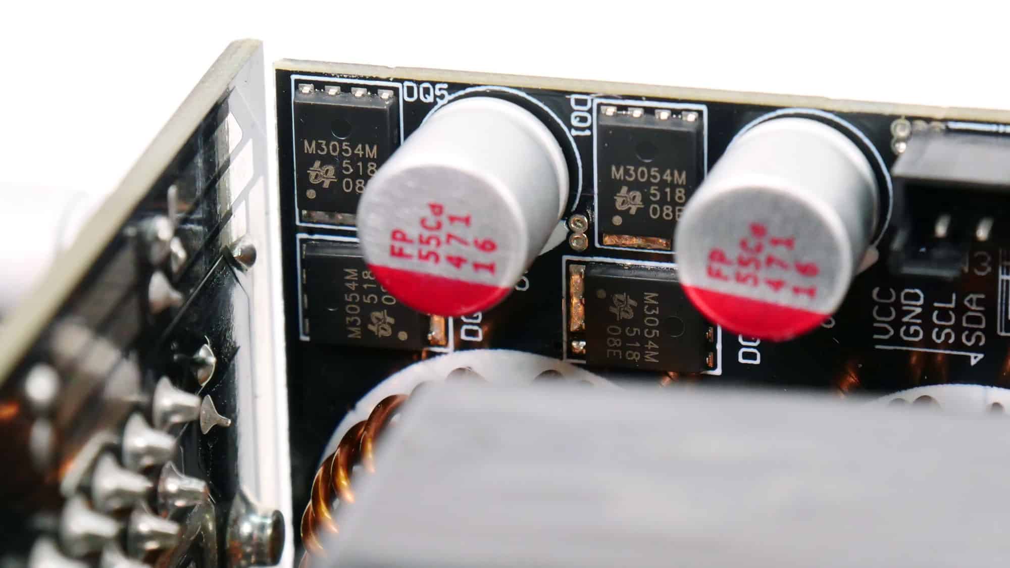
Two DC-DC converters generate the minor rails. They use four UBIQ Semi QM3054M6 FETs. The PWM controller is an Anpec APW7159C.
Chemi-Con, and Nichicon provide the electrolytic capacitors. Chemi-Con and FPCAP make the polymer capacitors. There are also two polymer caps, which I couldn’t identify (the OEM).
You can find more information about capacitor performance and other specs below:
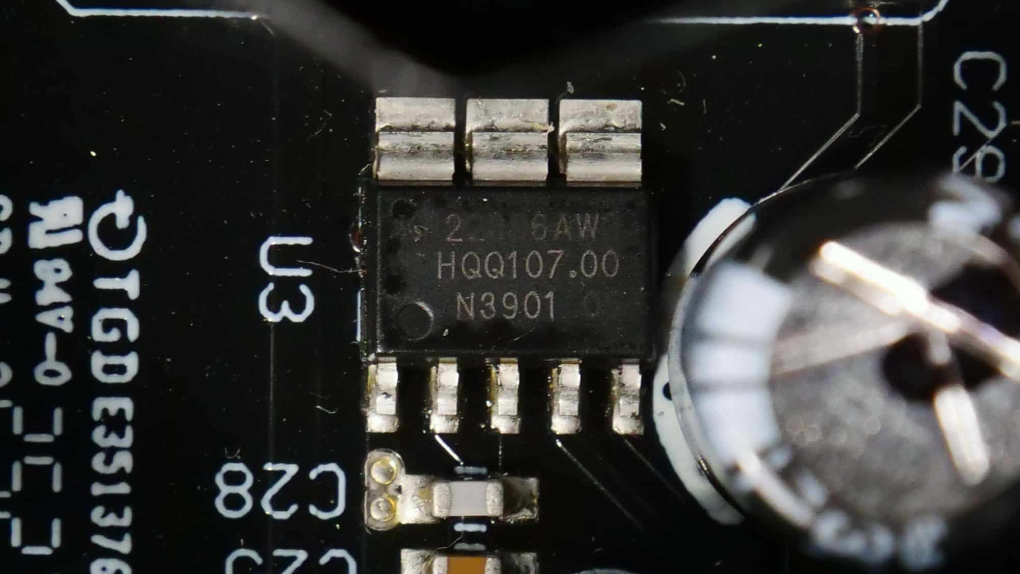
The standby PWM controller is a KP22306AWG.
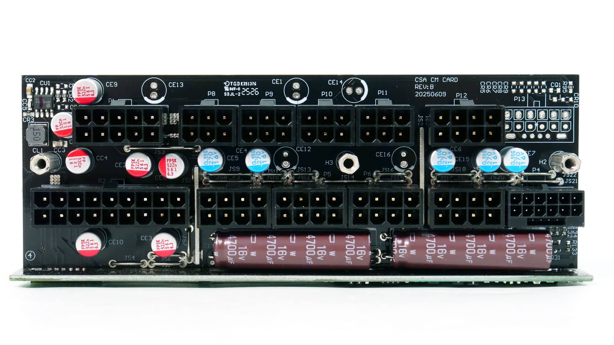
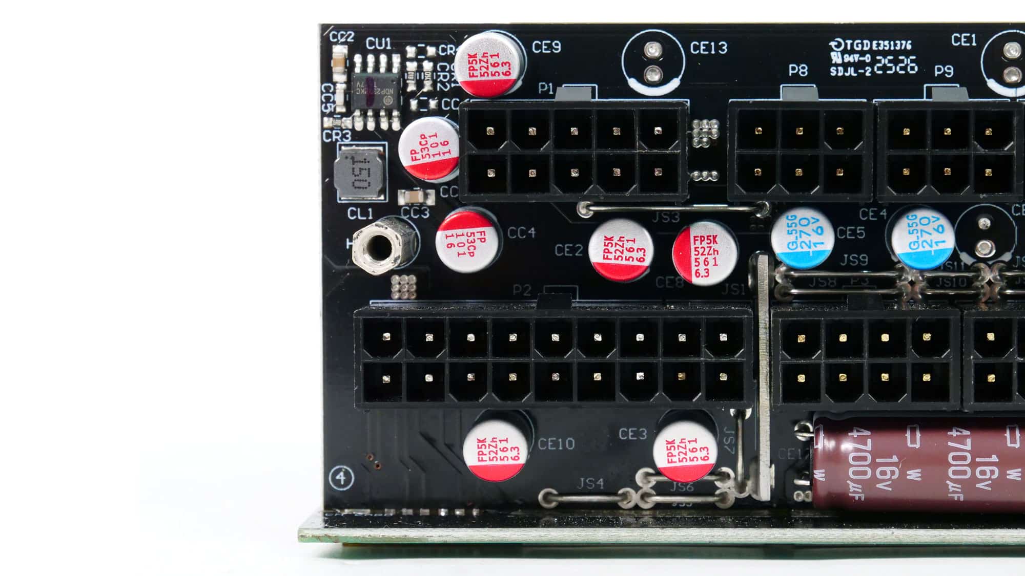
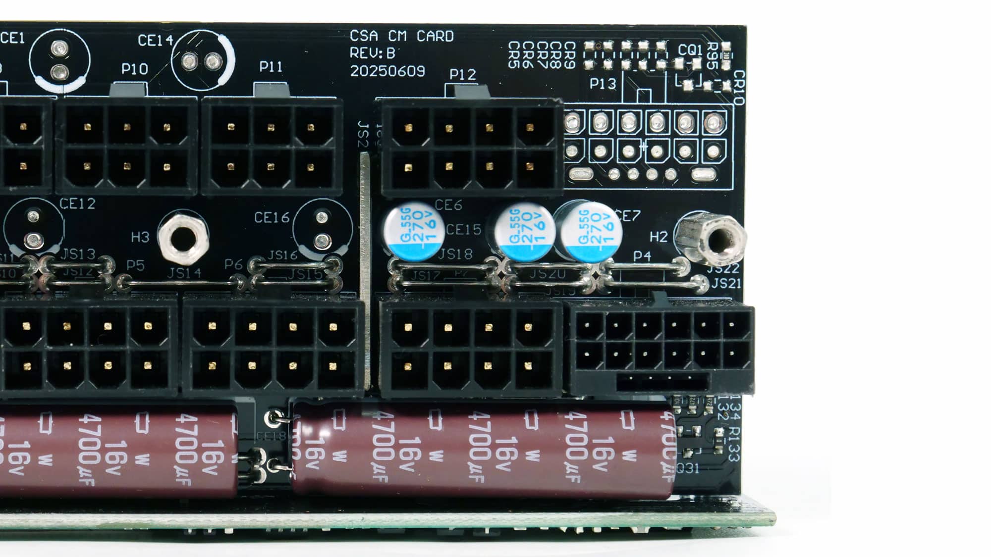
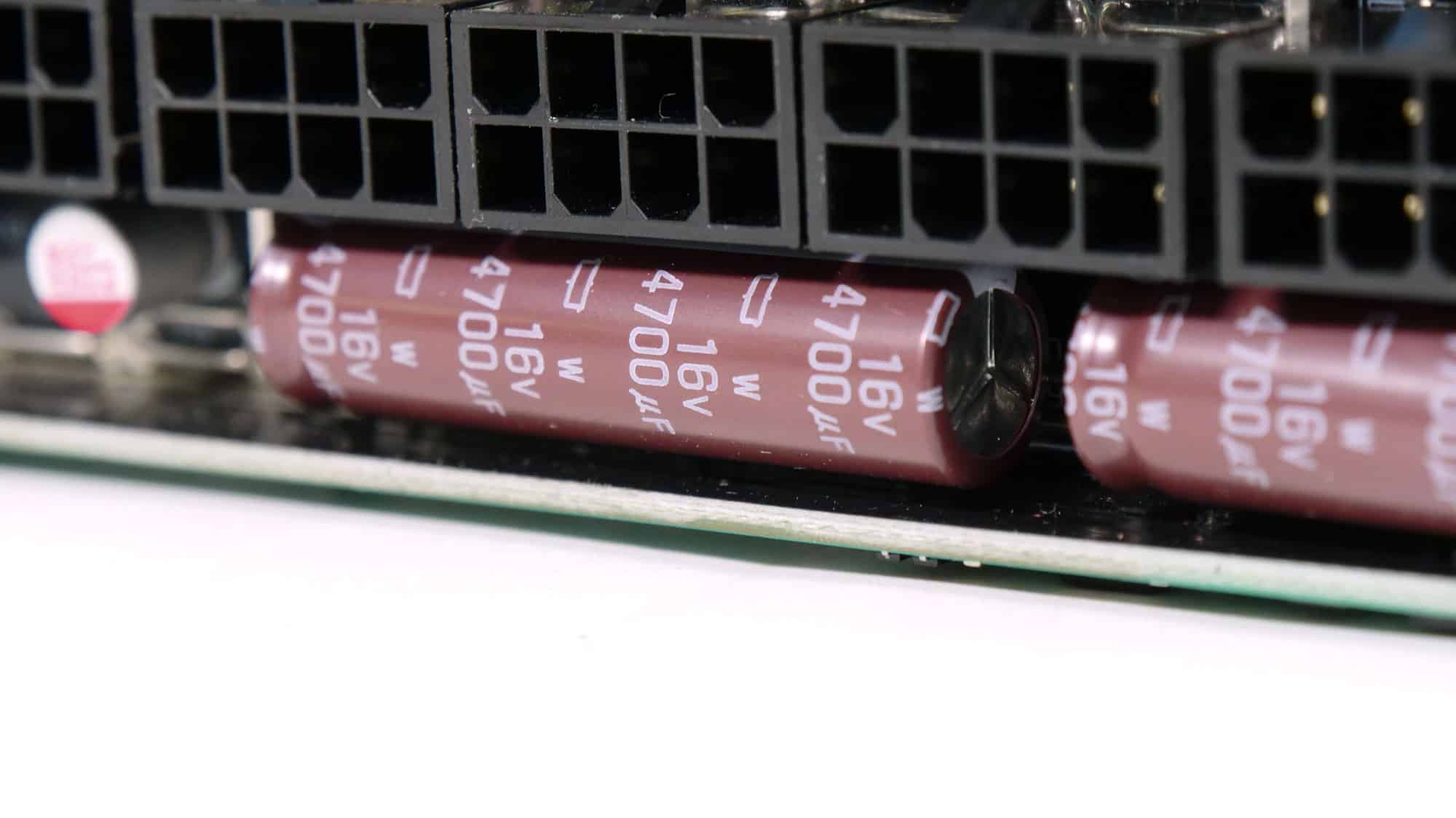
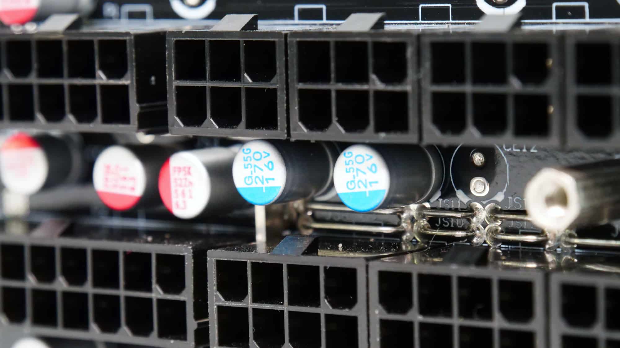
Several polymers and two big electrolytic caps on the face of the modular panel form an extra ripple-filtering layer.
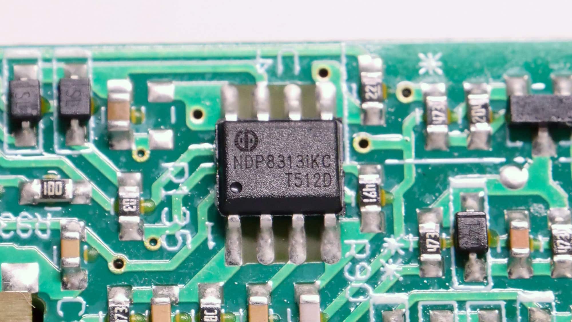
The supervisor IC is an NDP NDP8313iKC (OVP, UVP, SCP, PG). This is the first time I’ve encountered this supervisor IC (to the best of my knowledge), and there is nothing for it online. I will ask CWT to provide some more info on it.
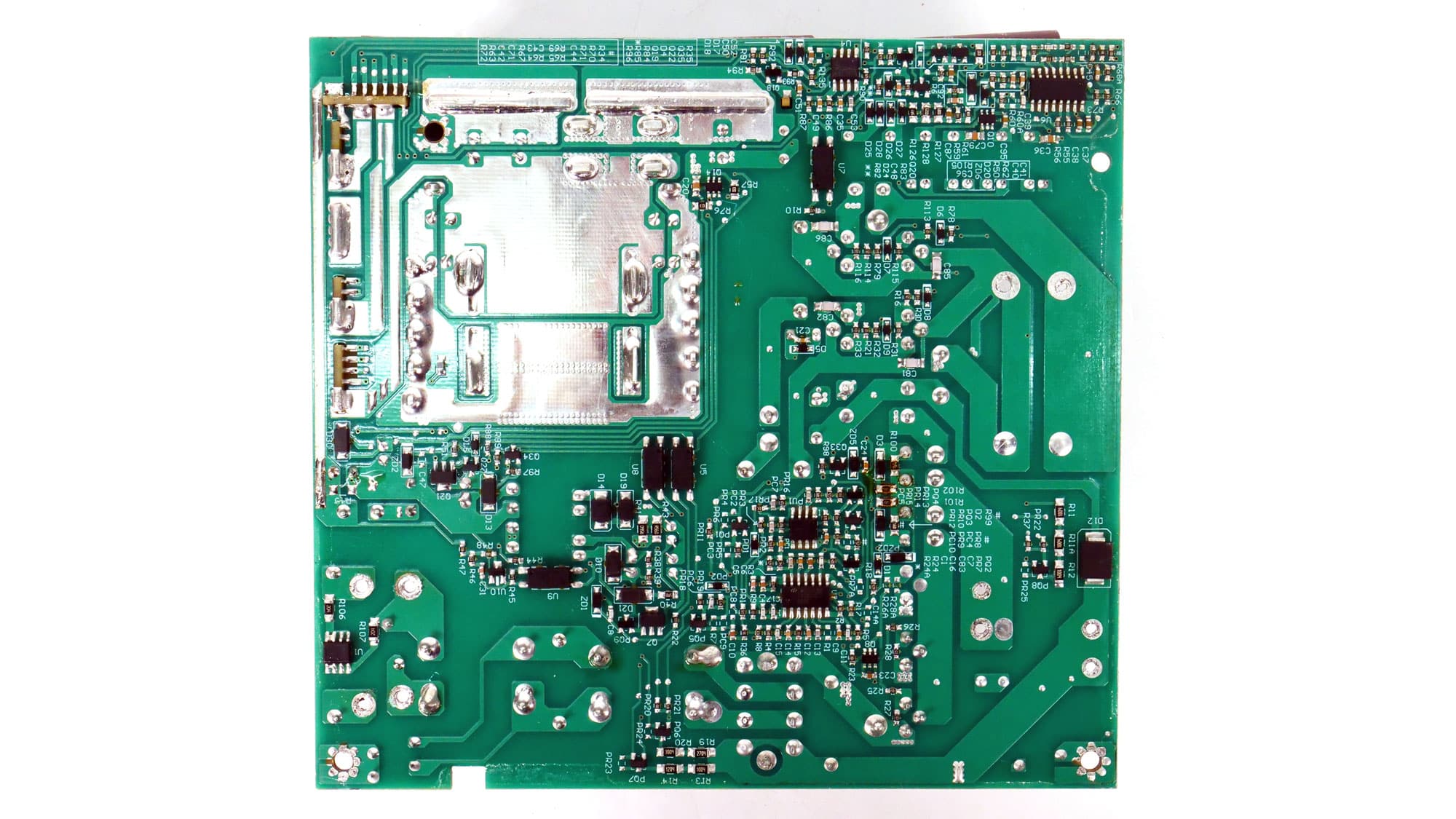
The soldering quality is similar to that of the 1000W model and notably better than what I encountered in the 1200W model.
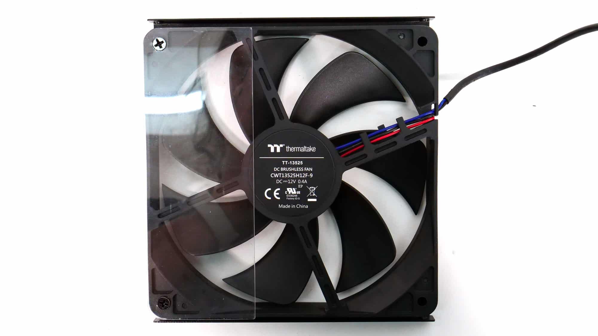
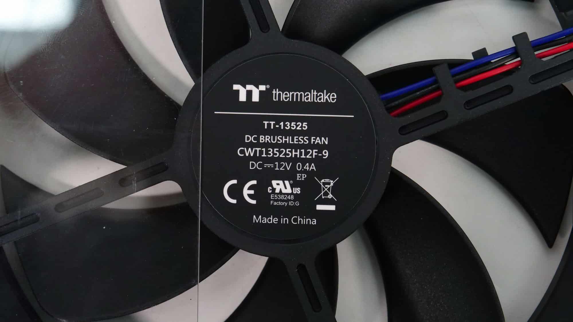
The cooling fan is a CWT13525H12F-9 that uses a fluid-dynamic bearing.
Will you have a written reviews on the recently released Dark Power 14 models? Thank you for your work on PSUs by the way and sorry for posting it here
I will start them now that I finished the PT series.
Cybenetics reports are up. 🙂