Hold Up Time
Hold-up time in power supplies is the duration a PSU can maintain a stable output voltage after a power interruption, allowing the system to shut down or ride out brief outages safely. It’s typically measured in milliseconds. A longer hold-up time is better, as it ensures continued operation during power fluctuations, preventing data loss or hardware damage.
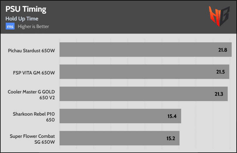
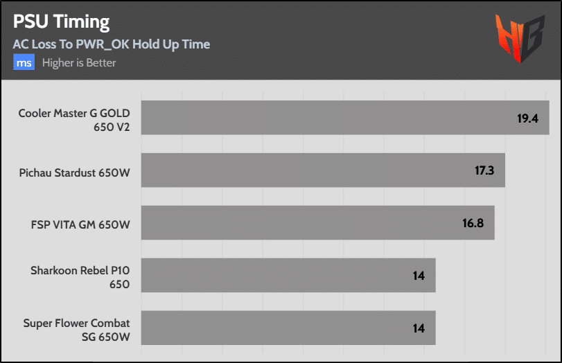
We couldn’t measure the hold-up time because the PSU’s EPS cable melted, so it wasn’t safe to apply a full load using only the remaining cables.
Inrush Current
Inrush current in power supplies is the initial surge of current drawn when a PSU is first powered on, caused by the charging of capacitors and other components. It’s typically much higher than normal operating current and lasts briefly. A lower inrush current is preferable, as high surges can stress components, trip circuit breakers, or cause wear over time.
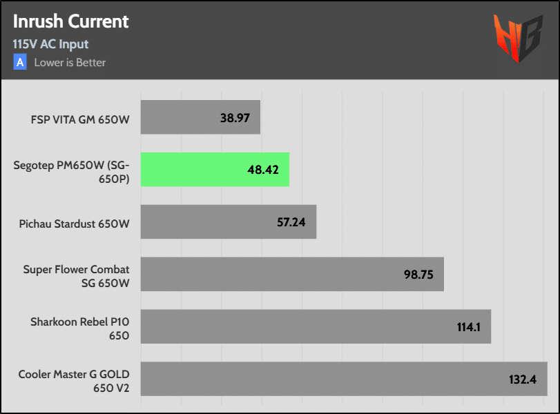
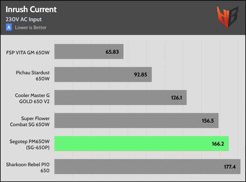
The inrush currents are low at 115V but are high at 230V.
Leakage Current
Leakage current refers to the small amount of current that flows through an insulating material or a semiconductor device when it is ideally supposed to be non-conductive. It is typically seen in electronics, such as transistors, capacitors, and insulators, where the current leaks due to imperfections or unintended pathways, even when the device is “off.”
Leakage current in power circuits is an alternating current that flows through the earthing conductor, primarily caused by the EMC filter’s Y capacitors (Cy). The more Y capacitors, the higher the leakage current can be!
The IEC 62368-1, which replaces the IEC 60950 OFF (Office Equipment) and IEC 60065 TRON (Electronics, entertainment), defines the limits for maximum leakage (touch) current.
- Normal Condition: Maximum touch current = 3.5 mA
- Single Fault Condition: Maximum touch current = 10 mA
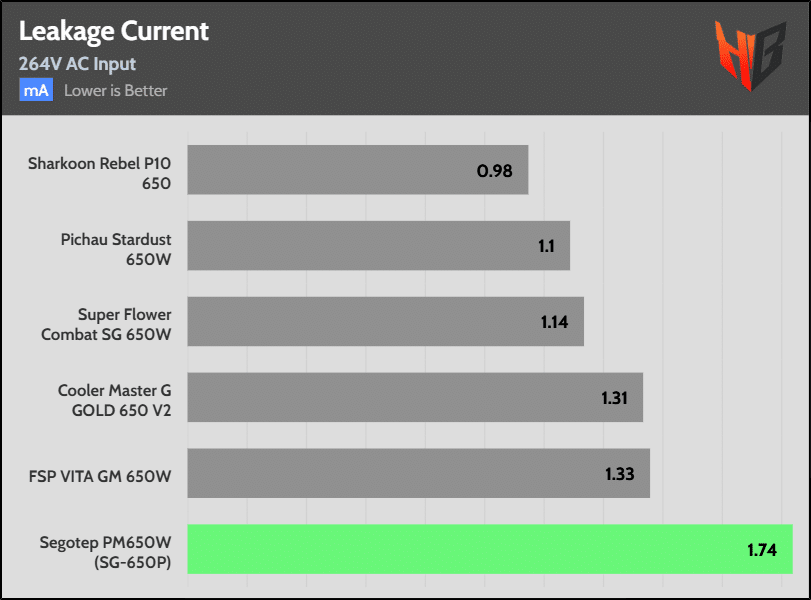
The leakage current has increased, but it is still well below the respective limit.
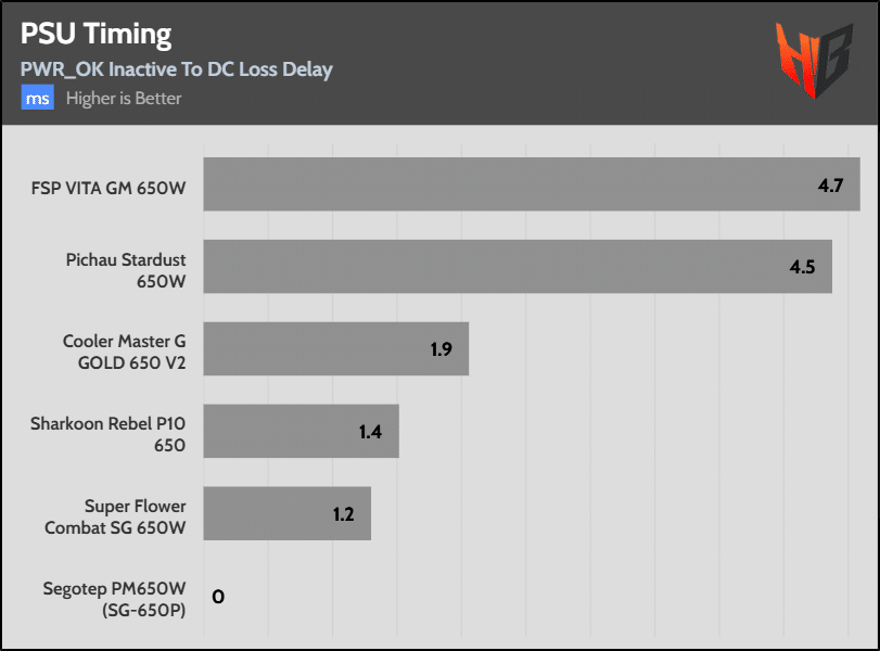
PSU Timings
Desktop PSU timings refer to the specific durations and sequences of electrical signals that a power supply unit (PSU) must maintain to ensure the proper operation of a computer system, as defined by the ATX specification. Proper timings are critical for system stability, preventing crashes or damage by ensuring components receive consistent, timely power.
In desktop power supply units (PSUs), Alternative Low Power Modes (ALPM), as defined in the ATX specification (e.g., ATX v3.1), are designed to improve energy efficiency by reducing power consumption during low-load or idle states, such as when a computer is in sleep or standby mode. These modes are closely tied to the T1 and T3 timings, which are critical for ensuring proper PSU behavior during transitions between power states.
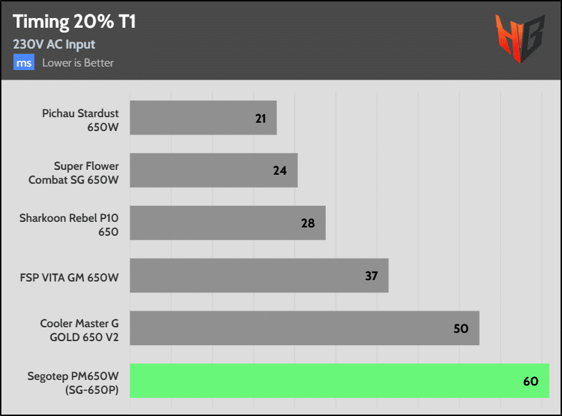
T1 and T3 Timings Explained
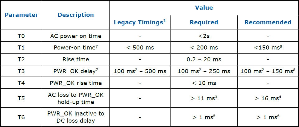
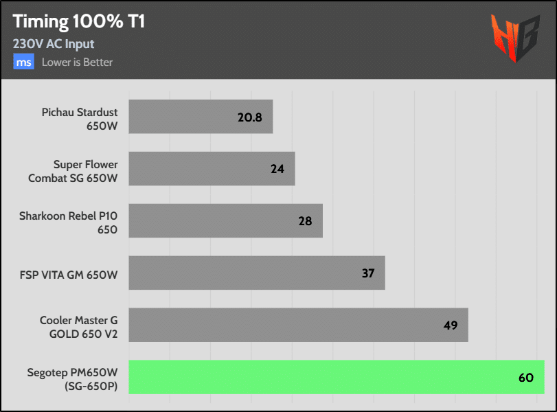
- T1 (Power-On Time): This is the time from when the PSU is turned on (via the PS_ON# signal going low) to when the output voltages are stable and within specification, and the Power Good (PWR_OK) signal is asserted. Typically, T1 is less than 500 ms, but it must be below 200 ms for ALPM compliance, and Intel recommends a value of below 150 ms. It ensures the system receives stable power quickly during startup or when waking from a low-power state.
- T3 (Power Good Delay): This is the time interval between when the output voltages reach their nominal levels and when the PWR_OK signal is asserted, typically ranging from 100 to 500 ms. For ALPM compliance, it has to be between 100-250 ms, with Intel recommending 100 – 150 ms. T3 ensures the PSU signals the system only when the power output is fully stable.
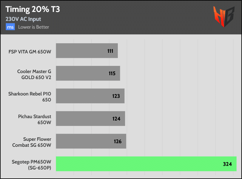
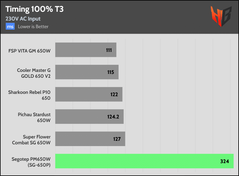
The PSU doesn’t support Alternative Low Power Modes.

Are you gonna review the FSP Mega Ti 1650W?
Once I find some time sure.