Part Analysis
| General Data | |
| Manufacturer (OEM) | Zhong Yuan Power |
| PCB Type | Double-Sided |
| Primary Side | |
| Transient Filter | 4x Y caps, 3x X caps, 2x CM chokes, 1x MOV |
| Inrush Protection | NTC Thermistor SCK-205R0 (5 Ohm @ 25°C) & Relay |
| Bridge Rectifier |
2x Yangzhou GBUL1506 (600V, 15A @ 100°C)
|
| APFC MOSFETs |
2x Sanrise SRC60R108BS (600V, 14A @ 125°C, Rds(on): 108mOhm)
|
| APFC Boost Diode |
Global Power G4S06508DT (650V, 8A @ 152°C)
|
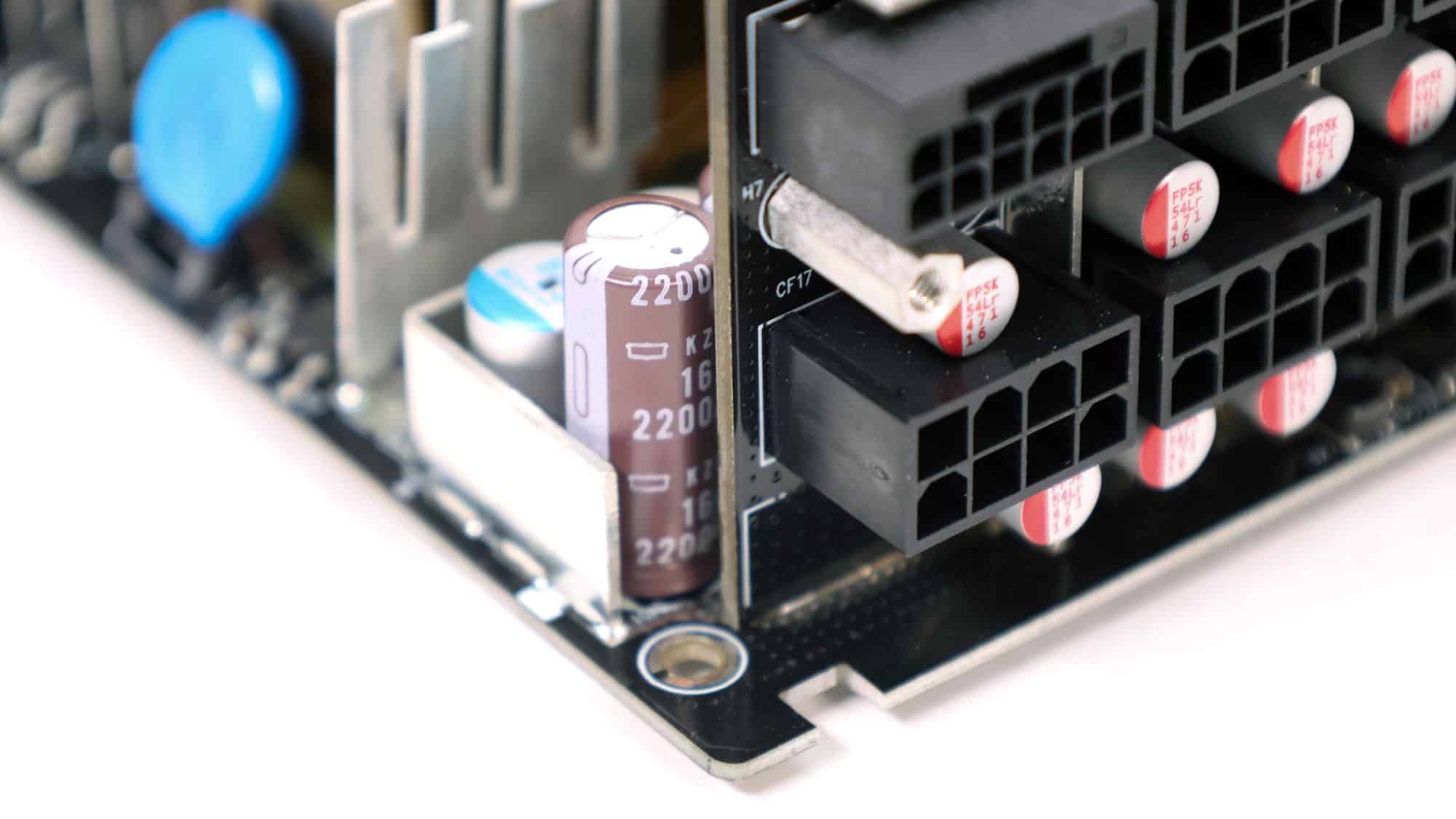
| Bulk Cap(s) |
Nippon Chemi-Con (400V, 680uF, 2,000h @ 105°C, KMW)
|
| Main Switchers |
2x Sanrise SRC60R108BS (600V, 14A @ 125°C, Rds(on): 108mOhm)
|
| APFC Controller | Infineon ICE2PCS01 |
| Resonant Controller |
Monolithic Power HR1213
|
| Topology | Primary side: APFC, Half-Bridge & LLC Resonant Converter Secondary side: [12V] Synchronous Rectification & [Minor Rails] DC-DC converters |
| Secondary Side | |
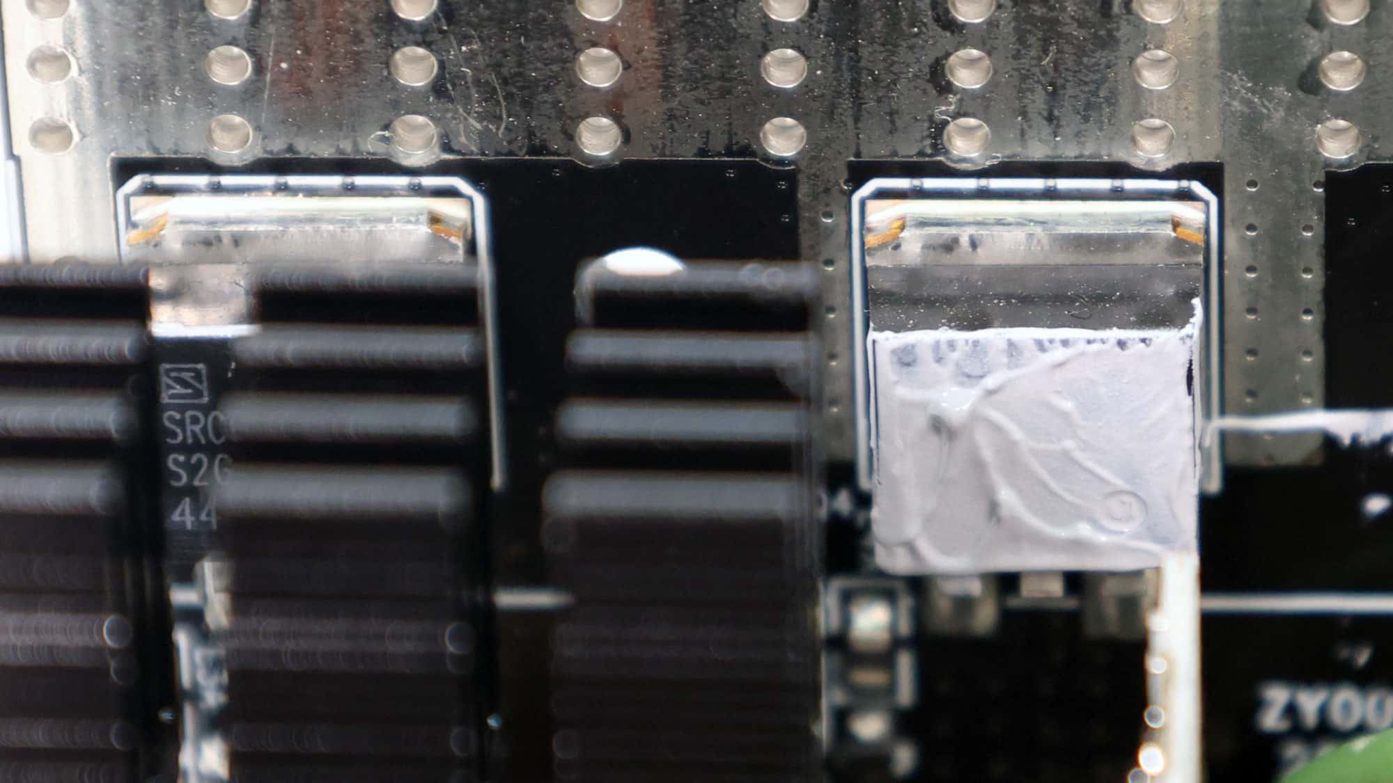
| +12V MOSFETs | 6x PSD PAS40N015CH |
| 5V & 3.3V | DC-DC Converters: 4x Maplesemi SLM100N03G PWM Controller(s): ANPEC APW7159C |
| Filtering Capacitors | Electrolytic: 4x Nippon Chemic-Con (2-5,000h @ 105°C, KZE) 2x Rubycon (4-10,000 @ 105°C, YXF) Rubycon (4-10,000 @ 105°C, YXJ) Rubycon (6-10,000 @ 105°C, ZLH) 2x no info Polymer: 11x Nippon Chemi-Con, 10x FPCAP |
| Supervisor IC | UTC8313 (OVP, UVP, OCP, PG) |
| Fan Model | Hong Hua HA1225M12F-Z (120mm, 12V, 0.45A, Fluid Dynamic Bearing Fan) |
| 5VSB Circuit | |
| Rectifier |
Dongke DK5V60R10VL (60V, 10mOhm)
|
| Standby PWM Controller |
Xuanyan XY6115
|
Zhong Yuan Power supplies this platform using an APFC, a half-bridge topology, and an LLC resonant converter on the primary side, which controls the primary switching FETs.
Resonance Converter Mini Tutorial
I write about LLC resonant converters in almost all of my reviews, but what is this circuit, and how does it operate?
What does resonance mean?
 |
 |
Resonance occurs when a system can store energy in two forms and exchange it back and forth at a specific natural frequency, called the resonant frequency. At that frequency, energy transfer is most efficient, and losses are minimized.
A Resonance Example
Think of a swing:
- You push at the right timing → the swing goes higher with minimal effort
- You push at the wrong timing → energy is wasted
That “right timing” is resonance.
Electrical resonance (LC circuits)
In electronics, resonance usually involves:
- L (Inductor) → stores energy in a magnetic field
- C (Capacitor) → stores energy in an electric field
At resonance:
- Energy moves back and forth between L and C
- The source supplies only the losses, not the full energy each cycle
Resonant frequency
At this frequency:
- Inductor current and capacitor voltage are perfectly coordinated
- Reactive energy cancels out
- The circuit behaves in a very efficient, predictable way
What happens at resonance:
- Current becomes nearly sinusoidal
- MOSFETs switch when the voltage is near zero (ZVS – Zero Voltage Switching)
- Switching losses and EMI are significantly reduced

Why resonance is useful!
Operating near resonance allows:
- ✔ High efficiency
- ✔ Low switching stress
- ✔ Lower EMI
- ✔ Higher switching frequencies without excessive loss
Instead of “forcing” energy through the transformer, the converter rides the natural oscillation of the LC network.
Takeaway
Resonance is the condition in which energy naturally oscillates between storage elements, allowing power to flow efficiently with minimal loss. LLC converters exploit this to achieve high efficiency and low EMI.
Back to the Part Analysis
The MOSFETs are not from a known manufacturer (e.g., Infineon) to keep costs down. This doesn’t mean, of course, that they won’t do their job without issues, at least under normal operating conditions. On the other hand, all capacitors on both the primary and secondary sides are sourced from reputable brands and are part of higher-end series.
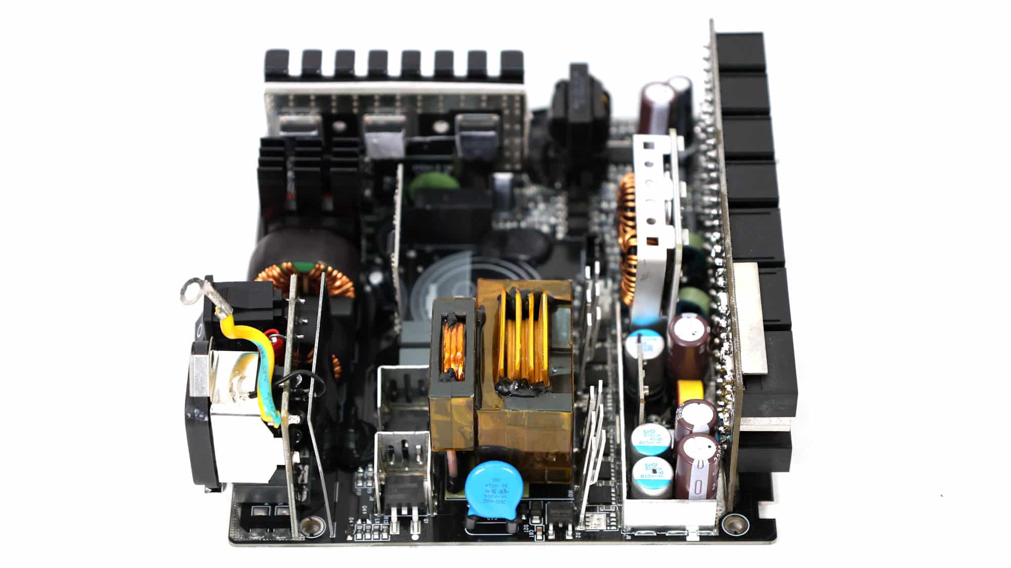
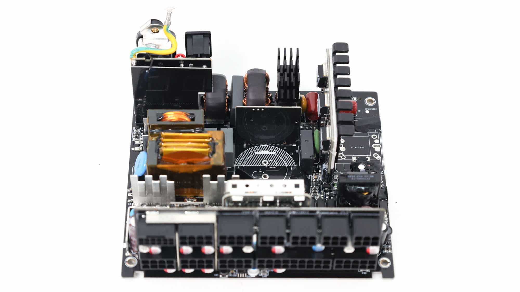
The small PCB is loaded with parts, yet it still provides good airflow to the filtering capacitors on its secondary side. The heatsinks are tiny, especially on the primary side, which saves space but makes cooling sensitive parts more difficult. Increased efficiency is the key here, keeping operating temperatures low without increasing the cooling fan’s load.
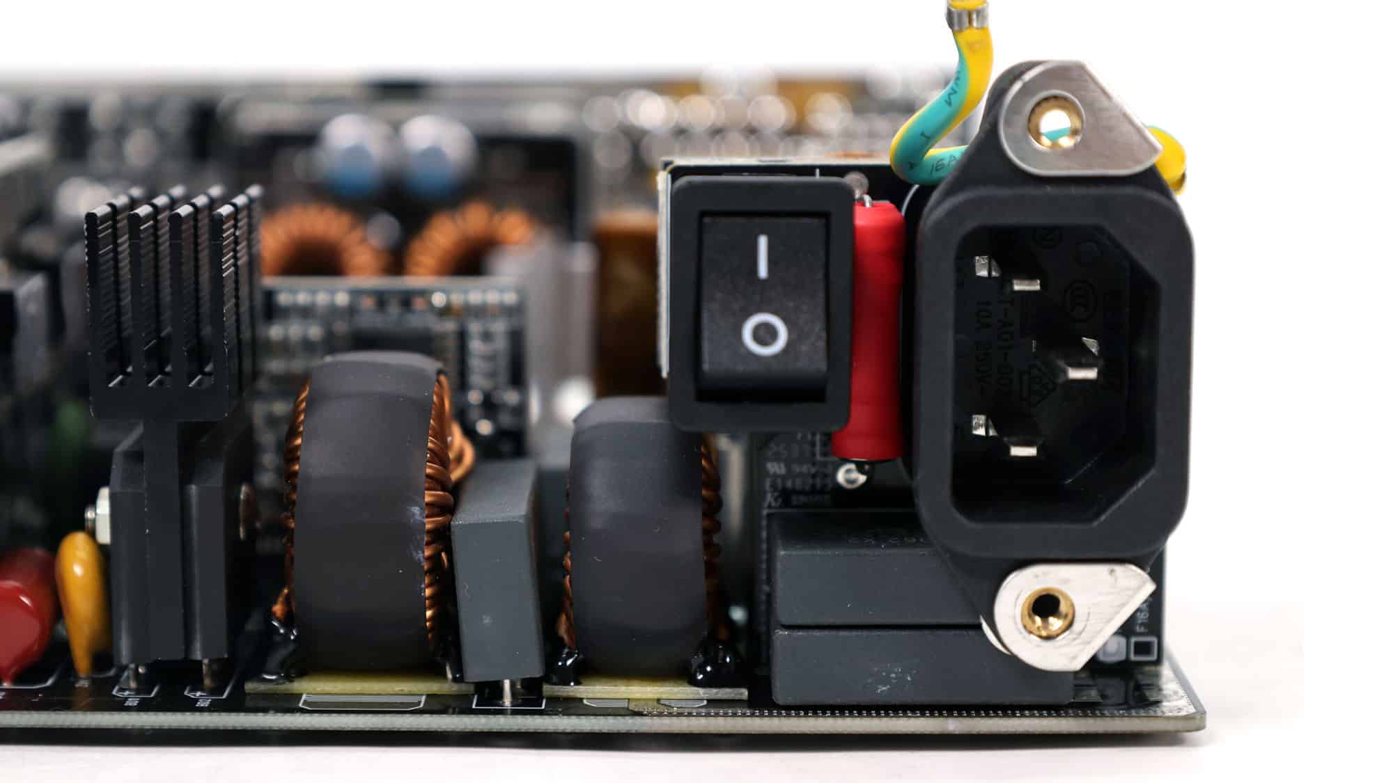

The transient filtering stage contains all the necessary components to block both incoming and outgoing EMI emissions. Typically, it starts at the AC receptacle and continues on the main PCB.
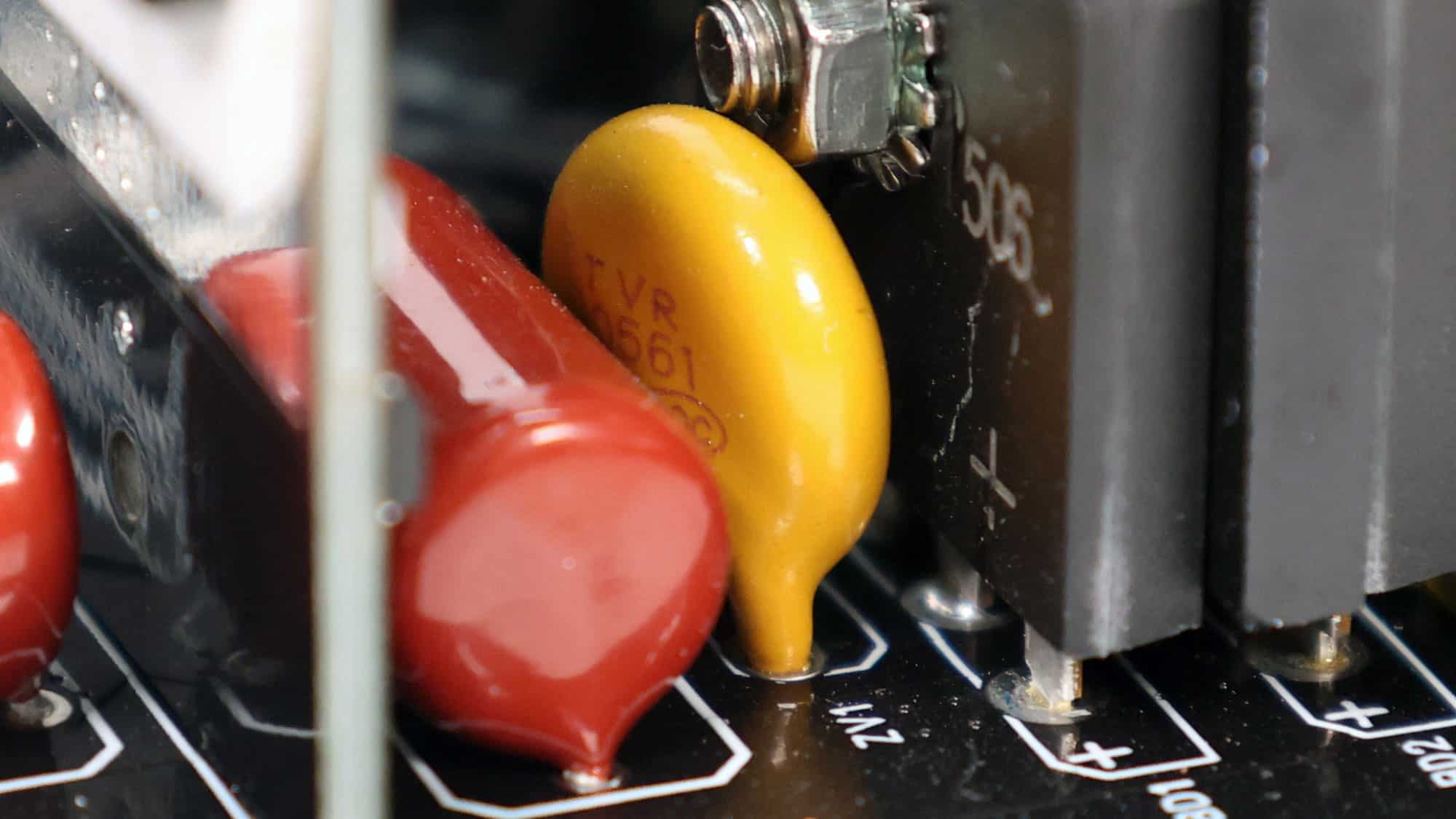
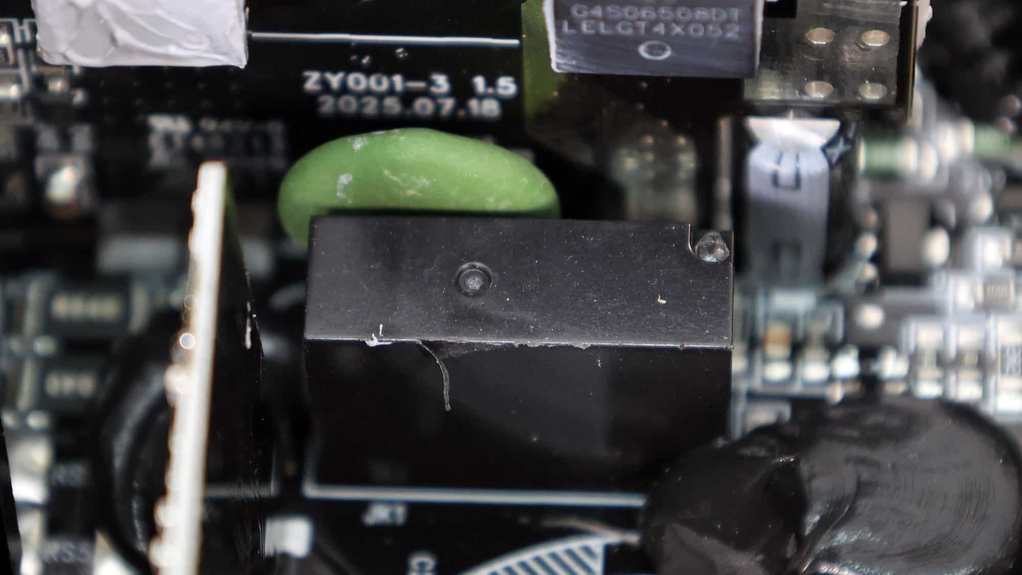
There is an MOV to protect from voltage surges and an NTC thermistor with a resistance of 5 ohms. Moreover, a bypass relay supports the NTC thermistor.
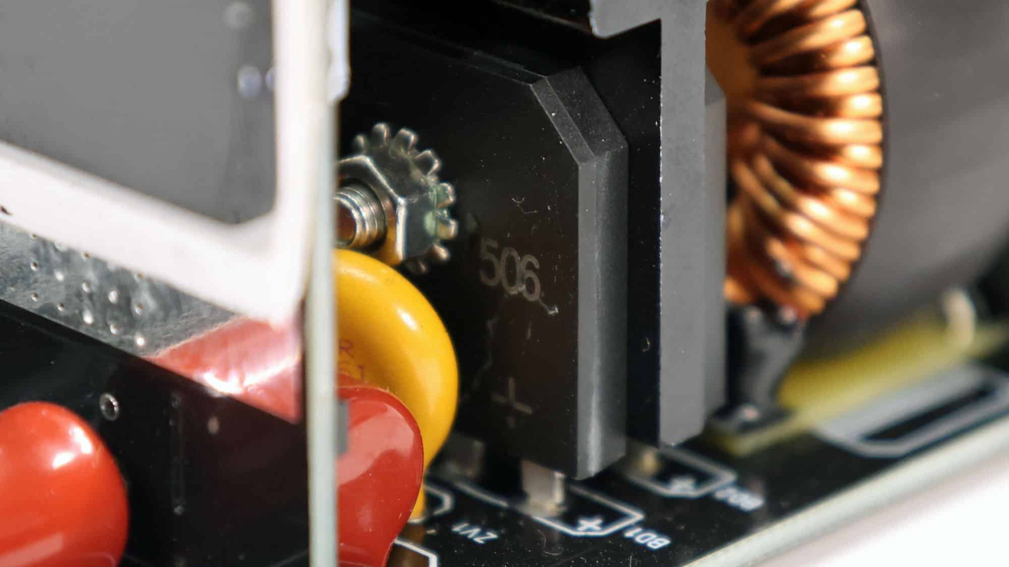
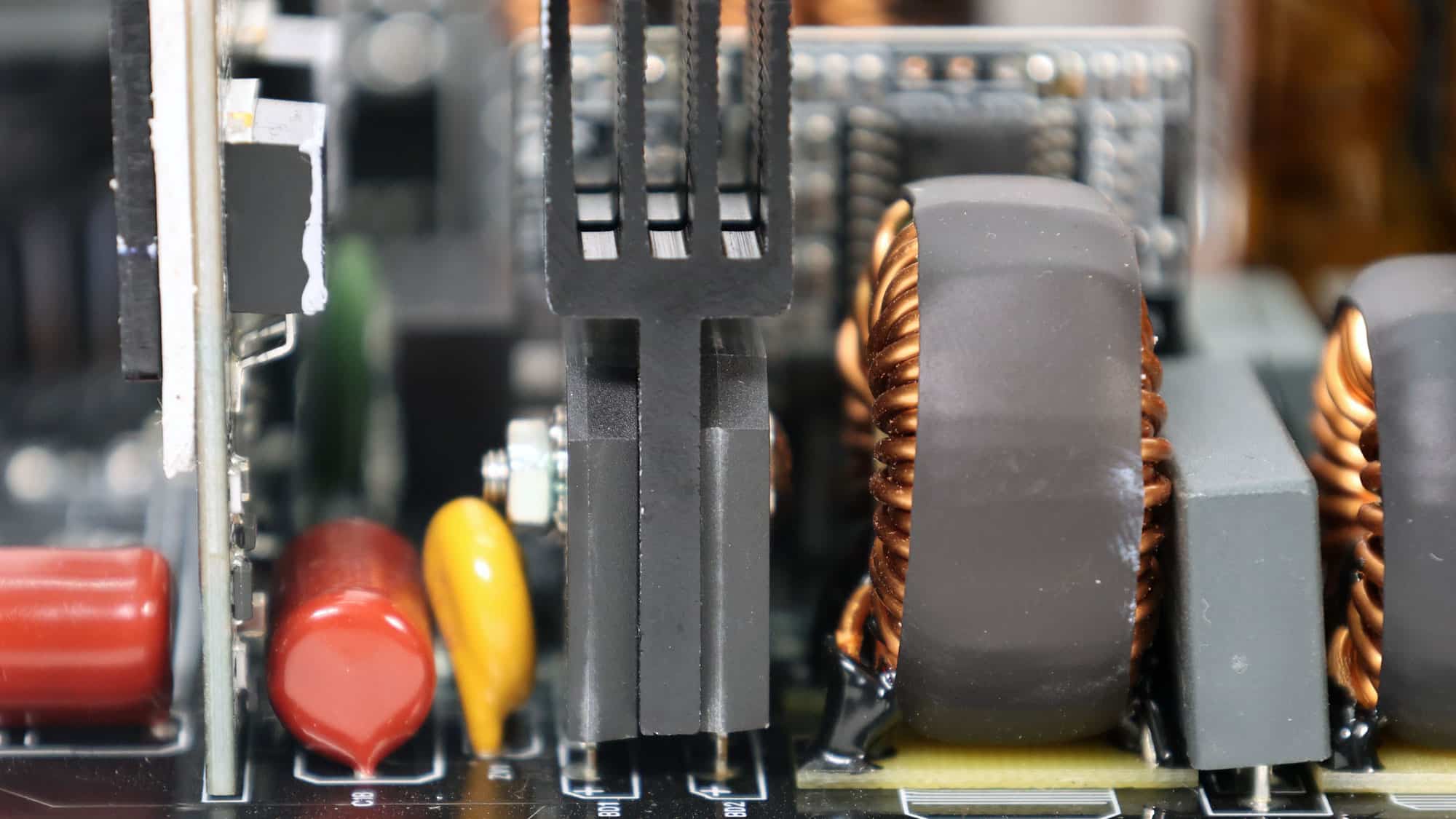
Two parallel bridge rectifiers fully rectify the incoming AC signal to a loosely regulated DC output.
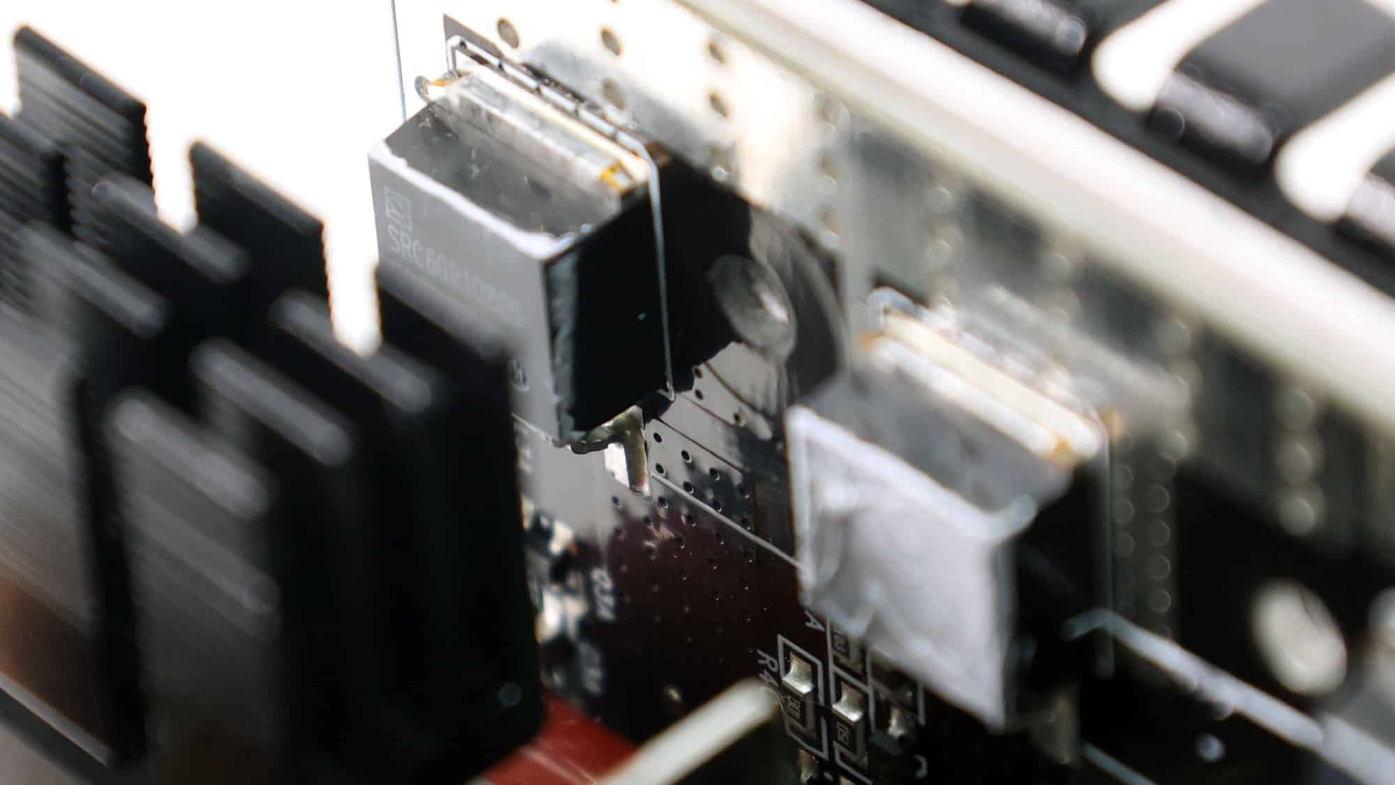
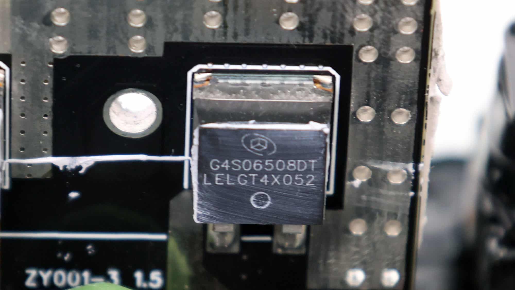
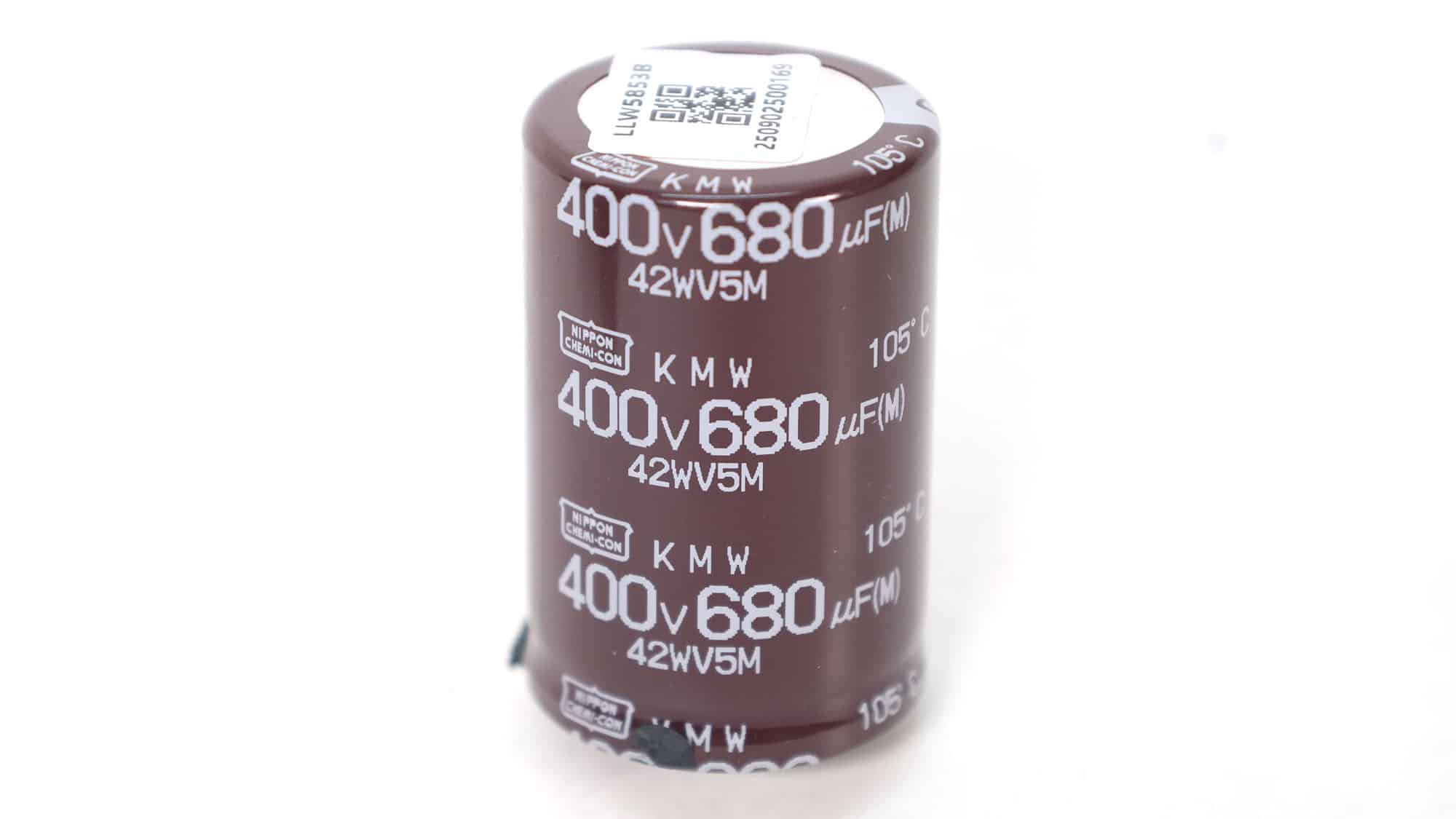
The APFC converter uses two Sanrise SRC60R108BS FETs and a single Global Power G4S06508DT boost diode. Chemi-Con manufactures the bulk capacitor. It has a capacity of 680μF and is rated for 2,000 hours at 105 °C. The voltage rating is 400V, providing a small margin from the APFC’s DC bus voltage (approximately 380-400V DC).
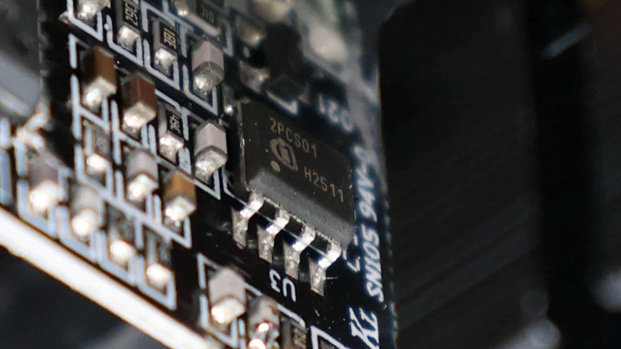
The APFC controller is an Infineon ICE2PCS01, which, in general, is more capable than the Champion CM6500UNX. The ICE2PCS01 explicitly supports the 50–250 kHz range. That’s handy if you want to push PFC frequency upward to reduce magnetics size/ripple, or tune for best efficiency + EMI compromise.
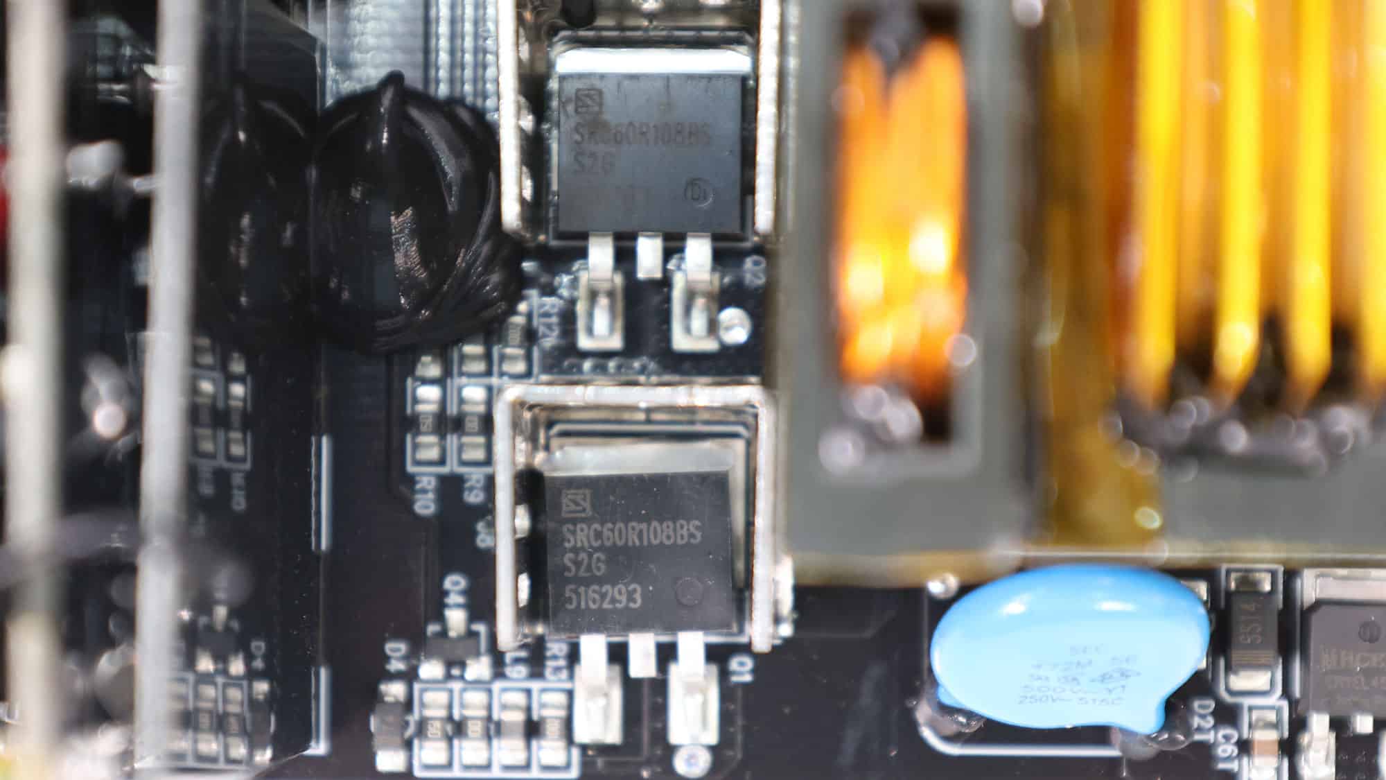
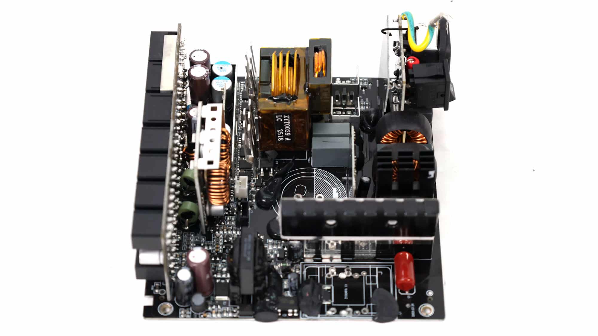
Two Sanrise SRC60R108BS primary-switching FETs are used in a half-bridge topology, and an LLC resonant converter is employed for enhanced efficiency.
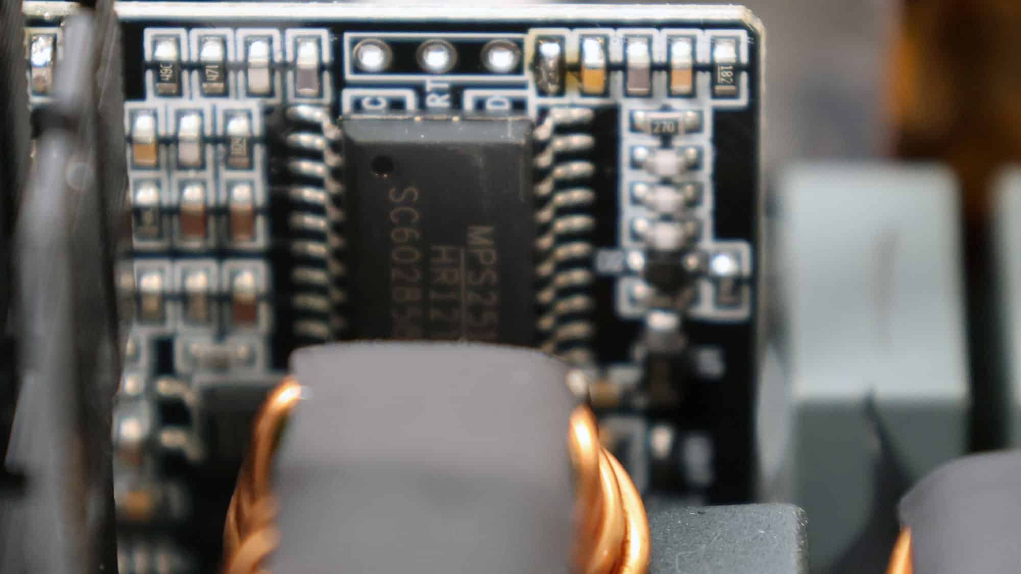
The LLC resonant controller is a Monolithic Power HR1213 instead of the typical one used in highly efficient PSUs, the Champion CM6901T2X. The HR1213 is a combo PFC/Resonant controller, but in this design, only the resonant part is utilized.
![]()
The PSU’s main transformer. One of its main functions is to isolate the primary and secondary sides electrically.
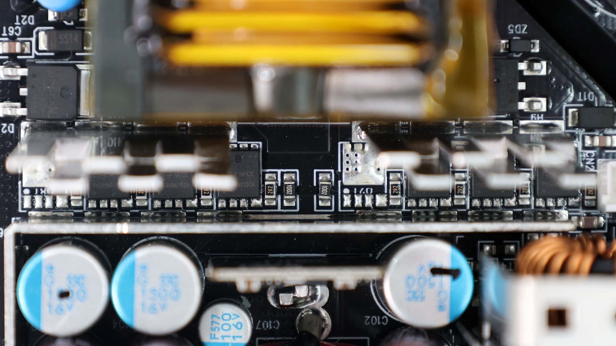
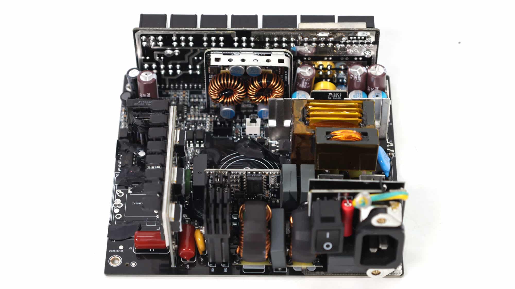
Six PSD PAS40N015CH FETs regulate the 12V rail. They are installed on the business (top) side of the PCB, and small heatsinks handle their cooling.
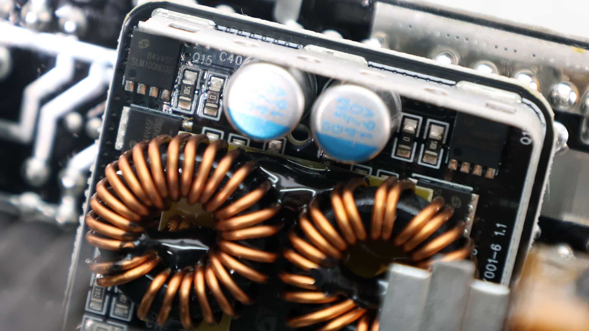
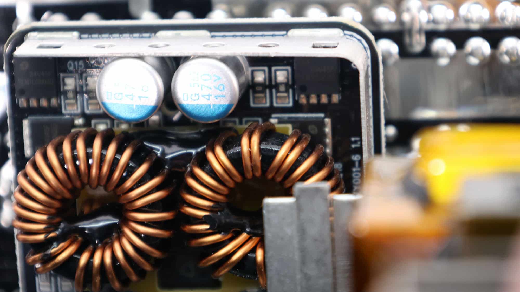
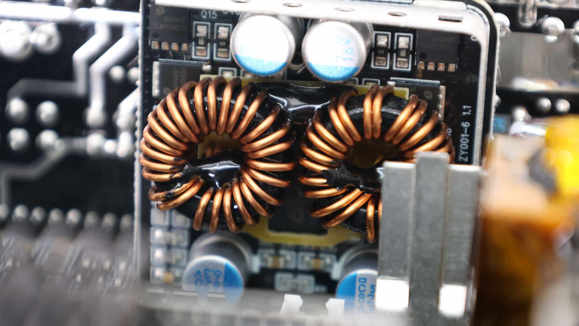
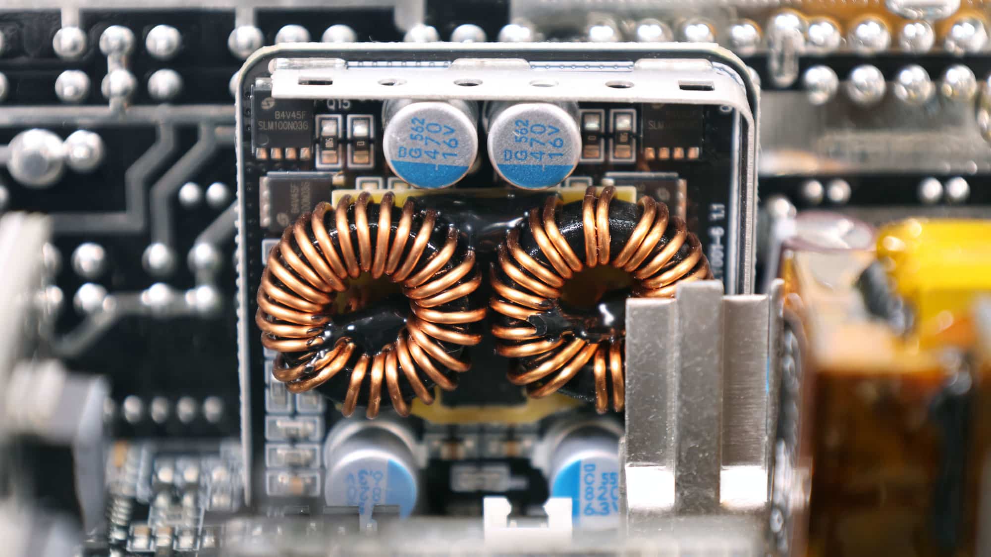
Two DC-DC converters generate the minor rails. They use four Maplesemi SLM100N03G FETs. The PWM controller is an ANPEC APW7159C.
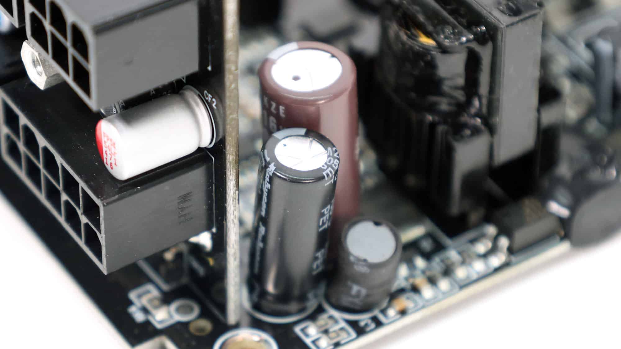
Rubycon and Nichicon provide the electrolytic capacitors. FPCAP and Chemi-Con make the polymer capacitors.
You can find more information about capacitor performance and other specs below:
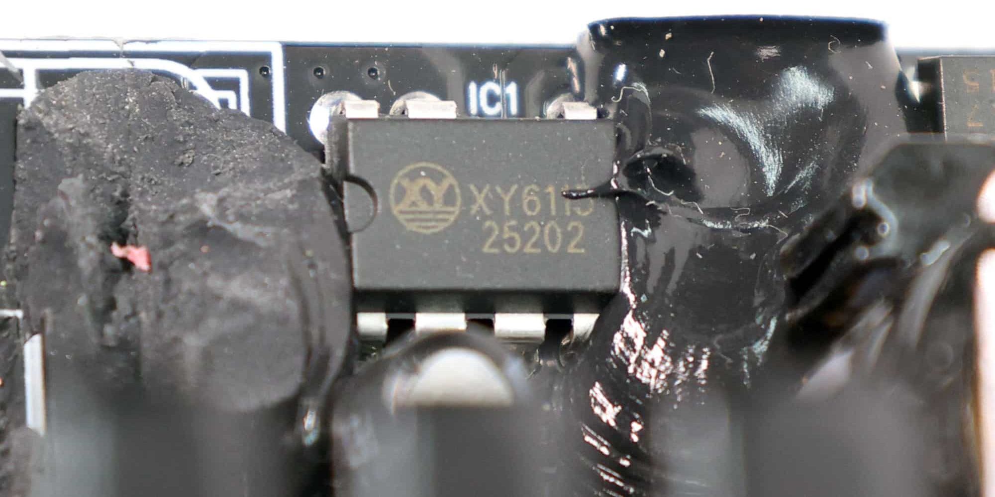
The standby PWM controller is an Xuanyan XY6115.
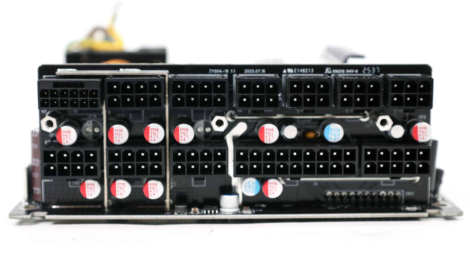
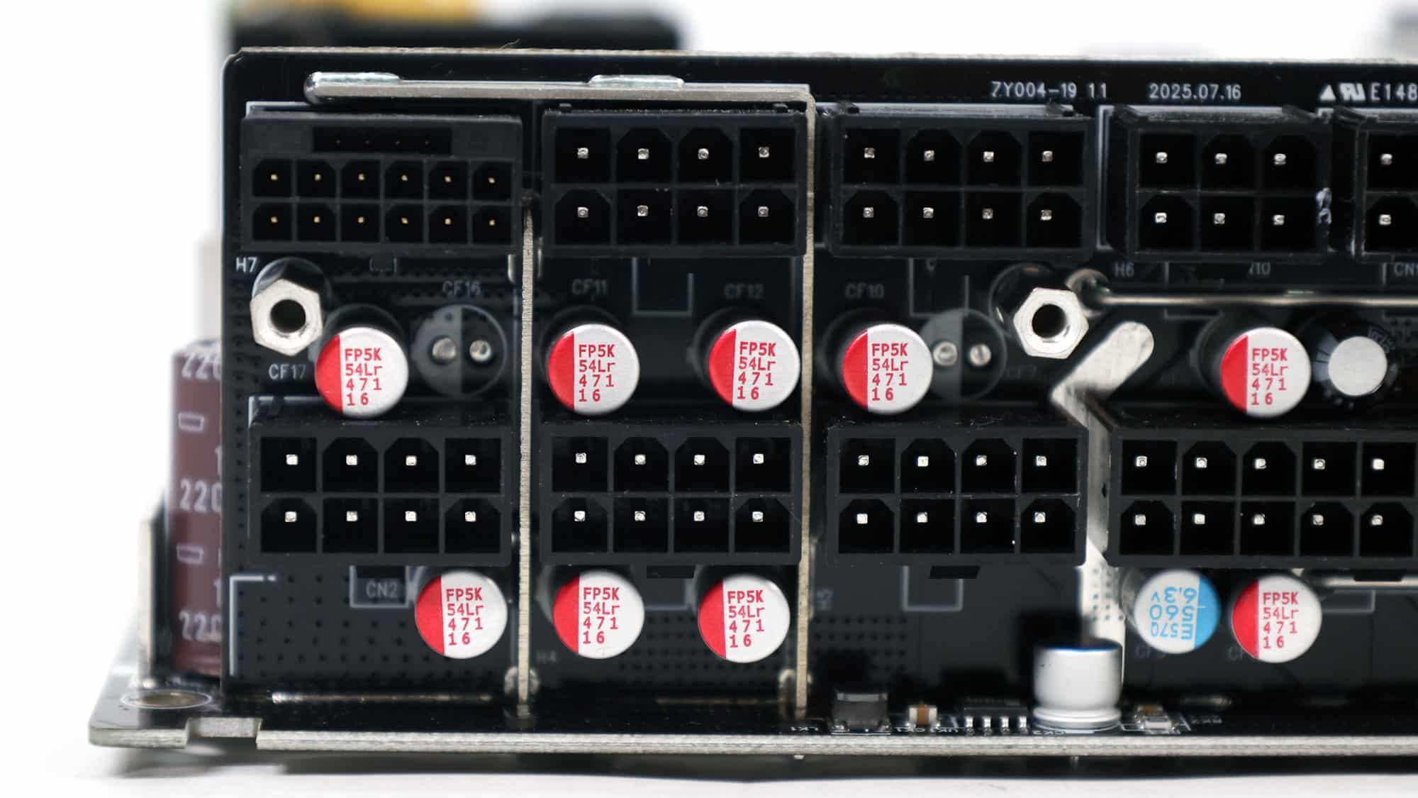
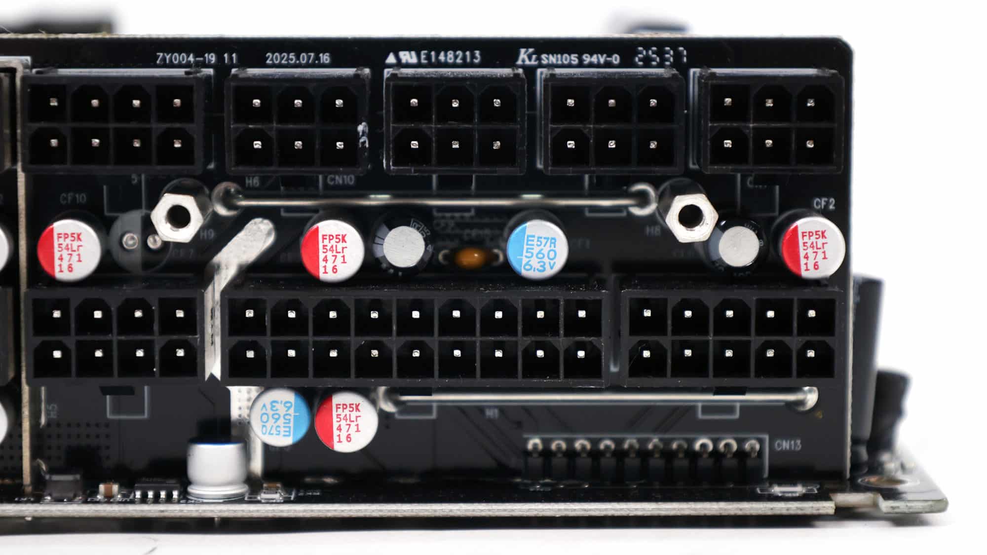
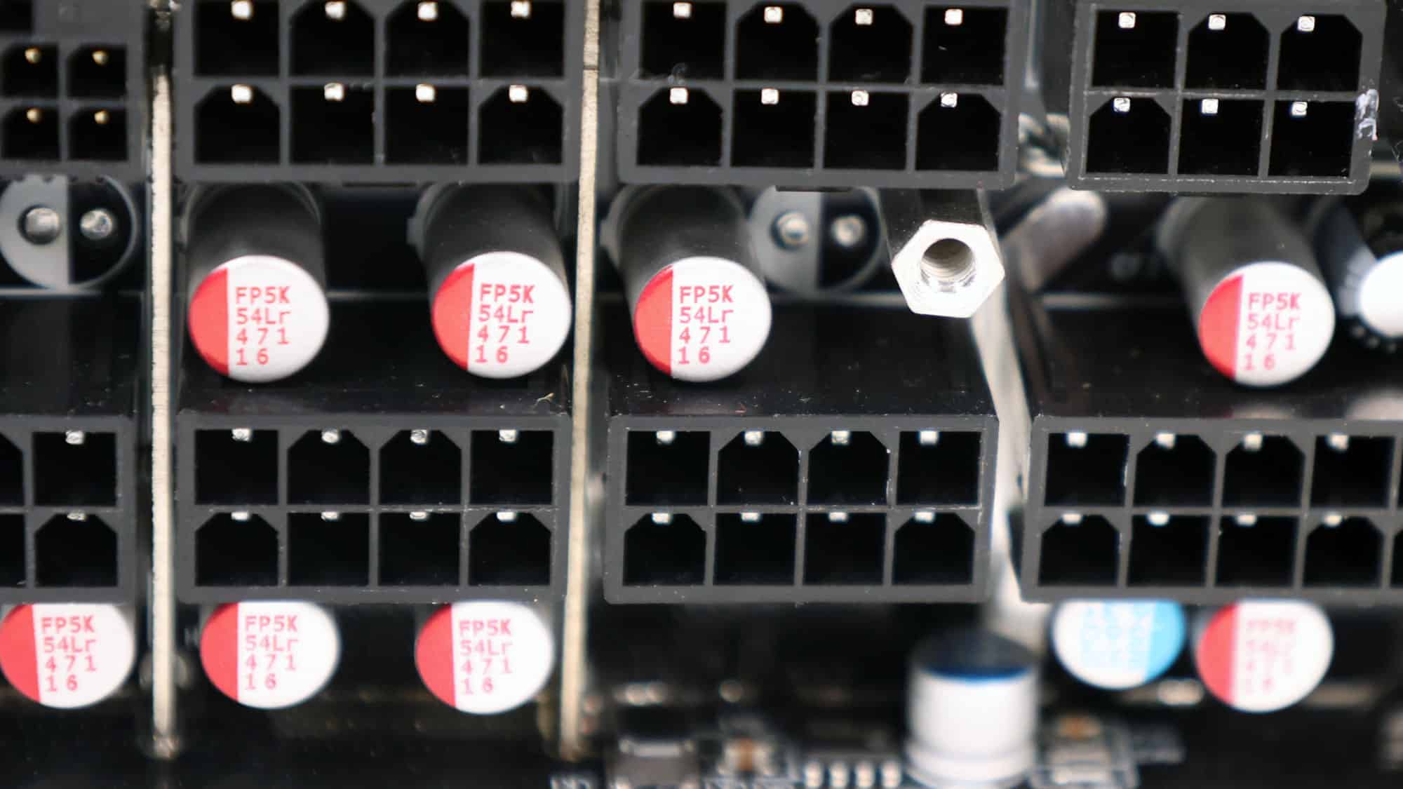
Several polymer capacitors on the modular panel’s face form an additional ripple-filtering layer.
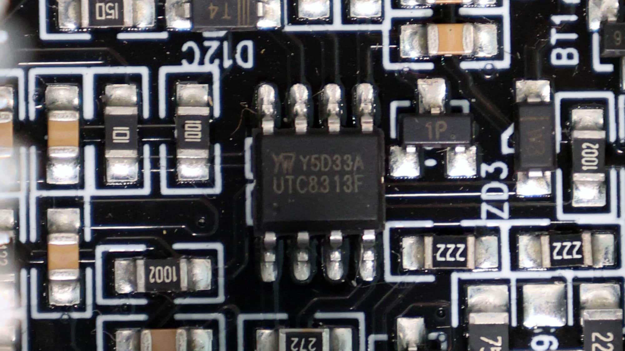
The supervisor IC is a UTC8313 (OVP, UVP, OCP, PG).
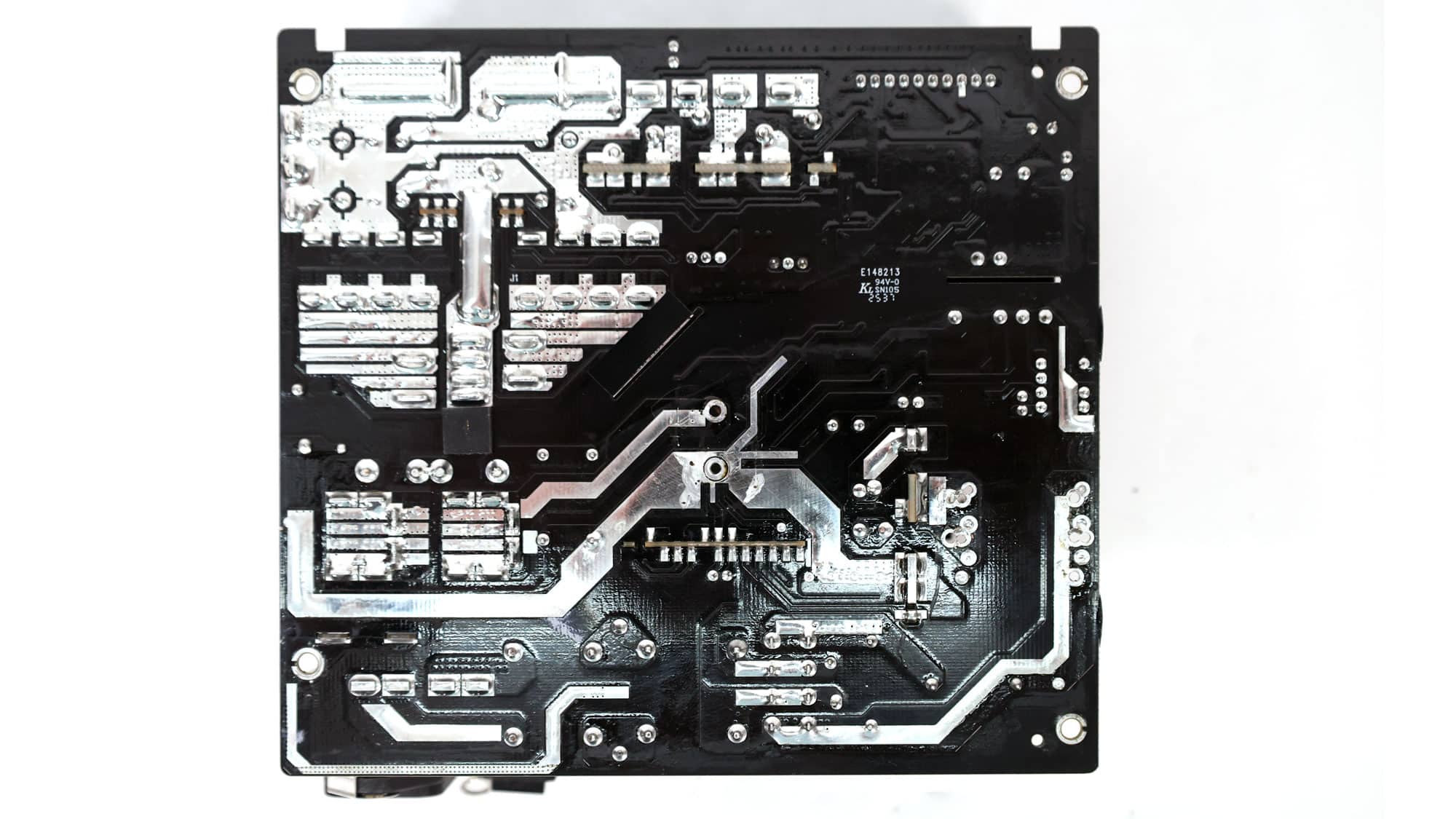
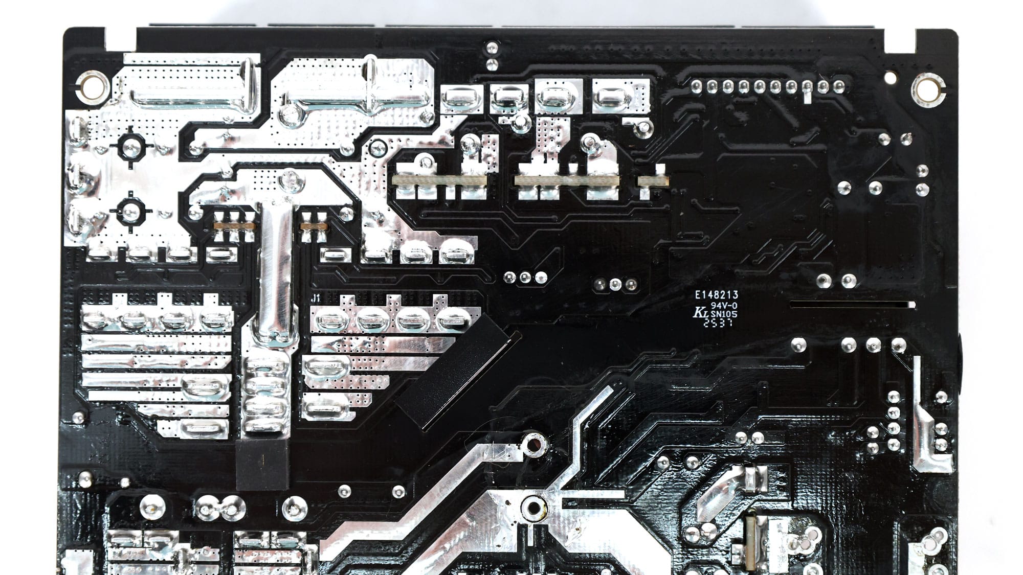
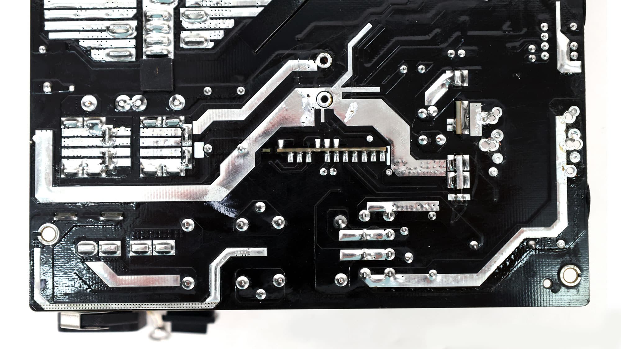
Soldering quality is decent in general. Moreover, there is not much to see on this side of the PCB. All parts are on the top side of the PCB.
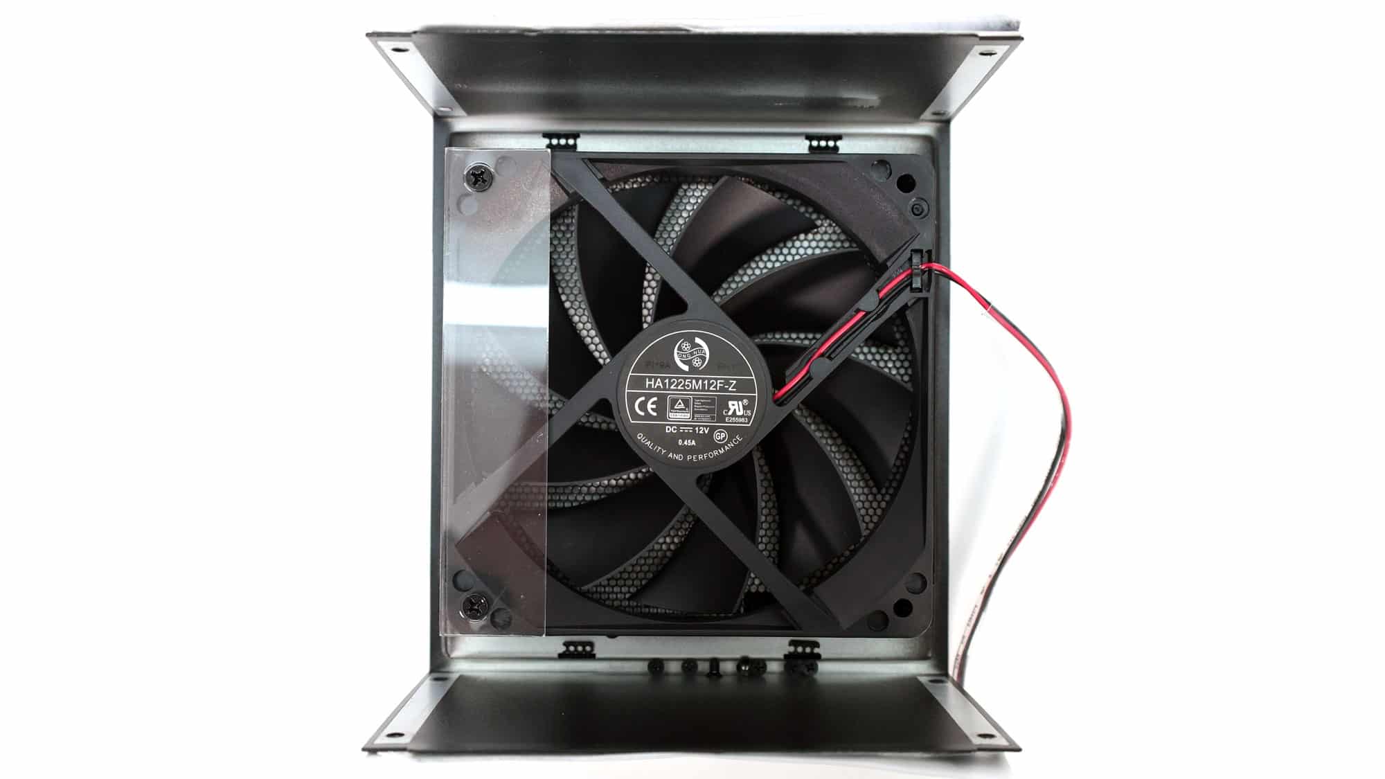
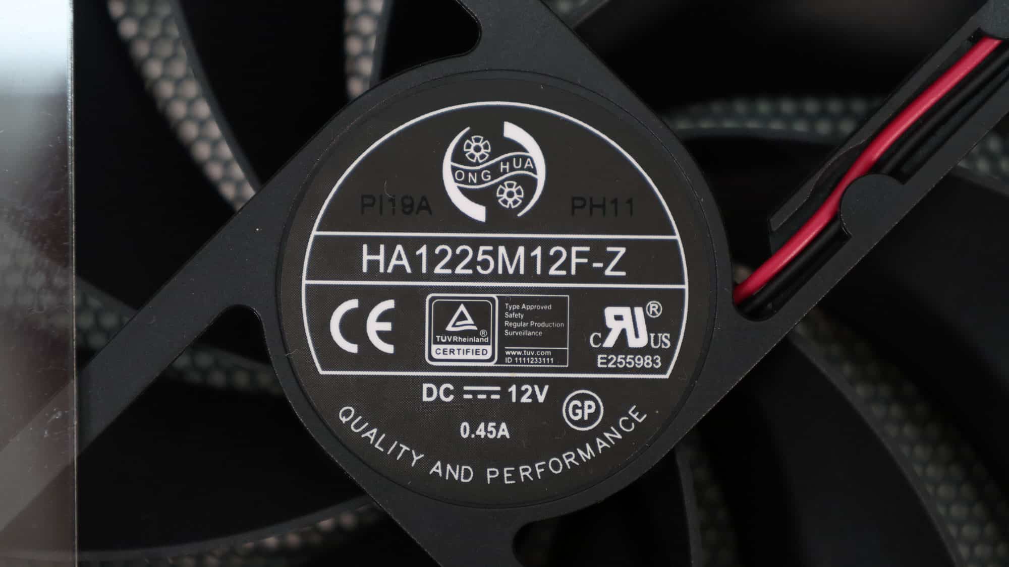
The cooling fan is a Hong Hua HA1225M12F-Z that uses a fluid-dynamic bearing.
such a good unit, price to performance was one of the best can’t wait to see in my country marketplace