In my recent PSU beta evaluations, I noticed something disturbing, in my opinion: manufacturers avoid using totem-pole PFC converters, which offer top efficiency, even though they integrate GaN FETs in their designs. Why does this happen? Let’s take a quick look at the possible explanations.
Much higher design complexity
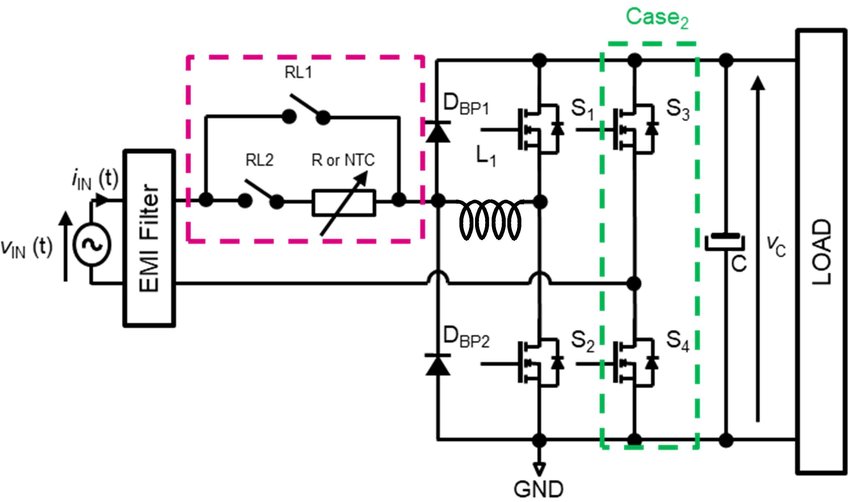
Totem-pole APFC replaces the diode bridge rectifier with actively switched MOSFETs. This means:
- Precise synchronous switching at line frequency
- Careful dead-time control to prevent shoot-through
- Tight coordination between slow (50/60 Hz) and fast switching domains
- A small timing or control error can instantly destroy power devices.
So practically with even a light timing error a totem-pole PFC goes boom. Given the extended period that users keep their PSUs and the instabilities in the mains grids, problems can occur in the long run.
Requires fast (and expensive) switches
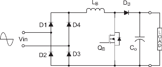
Silicon MOSFETs struggle with reverse-recovery losses in totem-pole designs. As a result:
- GaN FETs are almost mandatory for high efficiency
- GaN adds component cost, layout sensitivity, and manufacturing risk
- Gate-drive design becomes critical and unforgiving
- For mass-market PSUs, this cost jump is hard to justify.
As I mentioned already, I have seen some PSUs using GaN FETs, but without a totem-pole PFC. This means that they don’t exploit the assets that the MODFETs offer, although the manufacturers paid already their increase price, to install them in their platforms.
Harder EMI compliance
Totem-pole PFC generates:
- Higher common-mode noise
- Faster voltage edges (especially with GaN)
- More complex EMI filter interactions
Passing EN 55032 / CISPR 32 is noticeably harder than with a classic diode-bridge PFC. Being compliant with these two standards is crucial, else the products cannot be sold, certified, or legally placed on the market in many regions.
Standby power design becomes difficult
In bridgeless PFC:
- The AC input is never fully isolated from the switching network
- Leakage paths and parasitic currents increase
- Meeting <0.5 W standby power limits is harder
This forces more complex auxiliary and bias supplies. In general, the standby circuit is of utmost importance in a totem-pole PFC design. In totem-pole PFC, the standby rail is not just “wake-up power” — it is what keeps the active bridge under control, compliant, and safe at all times.
Lower robustness under abnormal conditions
Totem-pole PFC is more sensitive to:
- AC line distortion
- Brown-outs
- Inrush current events
- Surge and lightning transients
A diode bridge is inherently rugged; an active bridge is not. To further explain this: A diode bridge is more rugged than an active (MOSFET/GaN) bridge because it is passive, self-protecting, and failure-tolerant, while an active bridge depends on perfect control and timing.
Manufacturing and QA risk
Totem-pole designs:
- Are less tolerant to PCB variation
- Require tighter QA margins
- Have higher early-life failure risk if not perfectly tuned
This is a major concern for high-volume OEMs like Great Wall, CWT, HEC and others. It is not as easy as it sounds to have to keep the production line’s tolerances as tight as required to avoid reliability issues.
Bottom line
Manufacturers avoid Totem-Pole PFC not because it’s inferior—but because it is:
- More expensive
- Harder to design
- Harder to certify
- Less forgiving in production
- Only premium, low-volume, or ultra-efficiency-focused products can justify it.
Another thing that is not included in the list above but it is of high importance is the following:
A true totem-pole PFC cannot be controlled purely with an analog controller.
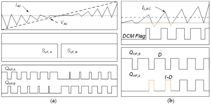
Why analog control doesn’t work someone could wonder. This is because totem-pole PFC requires:
- Line-cycle polarity detection
- Mode switching (CCM ↔ DCM / active ↔ passive leg)
- Precise dead-time control (nanoseconds, especially with GaN)
- Bidirectional current handling
- Dynamic EMI and fault management
All above functions are state-based and timing-critical, which analog controllers cannot reliably implement.